


6290W Touchscreen Home Security System
Installation Guide
https://mywebtech.honeywellhome.com
General Information 6290W Touchscreen
This guide provides information on installing and setting up the 6290W Touchscreen. The 6290W
Series graphical touchscreens are Advanced User Interface (AUI) devices, which combine control of
your security system and multi-media.
Software Information
: To check the latest software information, from the Home/Security screen,
select the Setup and System Info icons; the latest Software Version is displayed on the screen.
Compatibility:
For a list of alarm systems that the Touchscreen can interface with, refer to the
Compatibility Table in this document.
Wiring
IMPORTANT
: If you power the Touchscreen from your panel’s auxiliary power output, check your
panel’s Installation and Setup Guide and verify that this device and others do not exceed your panel’s
auxiliary power output capability; if it does, a supplementary power supply is needed.
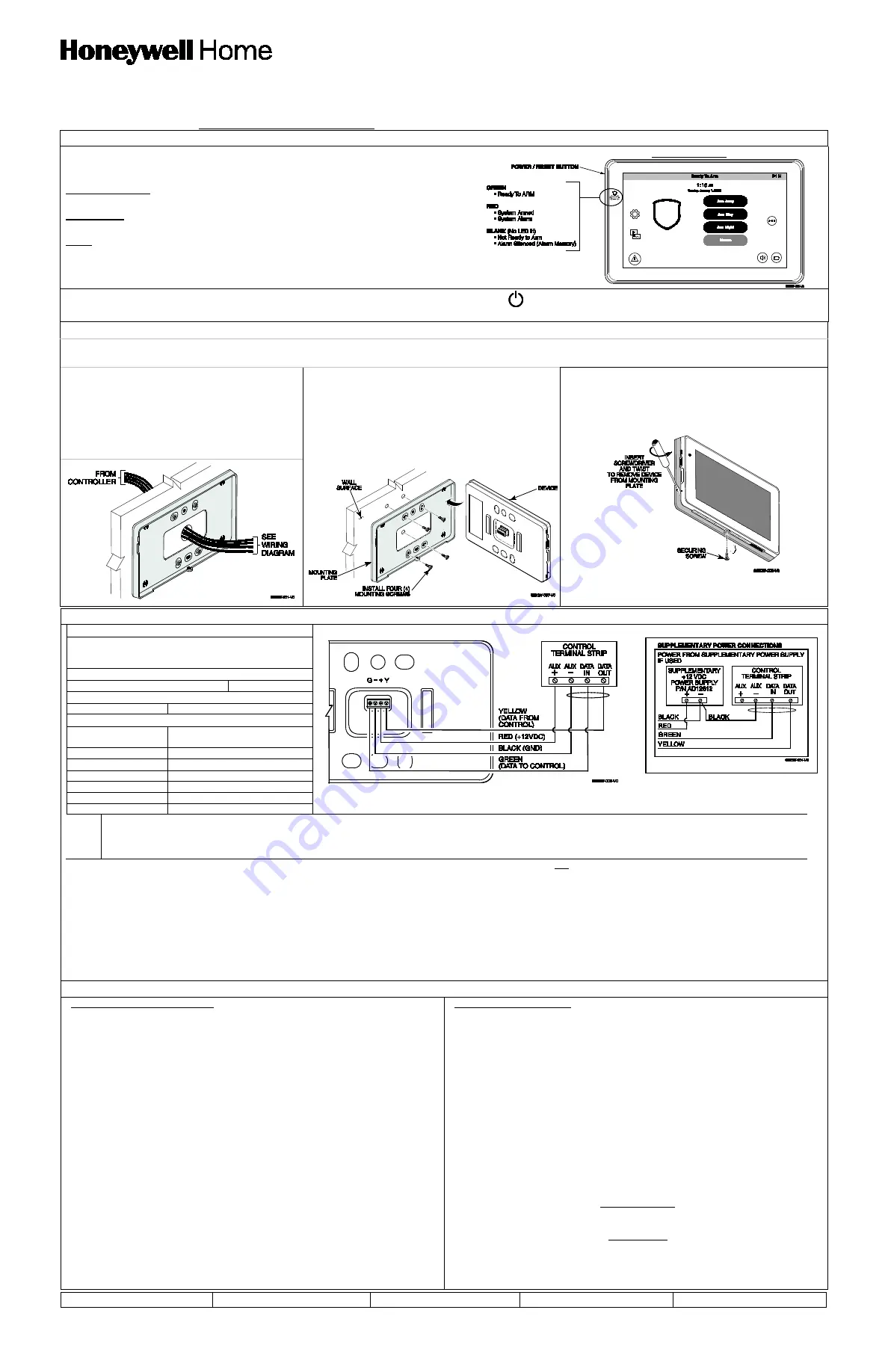
Front Panel LEDs
To reset the Touchscreen, press and hold the side Power button for 3 seconds and
t
hen select the reset button
on the screen to start the reset function. The Touchscreen can also be
reset by pressing and holding the reset button for approximately 15 seconds until the touchscreen resets automatically.
Mounting the Touchscreen
This Touchscreen is for indoor use only and should be mounted at a comfortable viewing level. Avoid mounting in areas of high condensation such as bathrooms or in locations where bright
light or sunlight shines directly on the screen. The Touchscreen is surface mounted directly to a wall.
Mounting:
1. Select a mounting location.
2.
Locate the case back over the mounting surface such that
the opening is aligned with the wire/cable access opening on
the mounting surface while passing the wires/cable through
the opening in the case back.
**
Go to “Wiring the Touchscreen” and complete wiring.
3. Secure the mounting plate to a mounting surface using 4
screws (supplied). Insert bottom edge of Touchscreen over
the mounting plate and then click in the top edge to snap into
place.
4. Install the cover securing screw at the bottom of the device to
secure. The bottom securing screw must be installed.
Removing the Touchscreen:
To remove the Touchscreen from its mounting location, insert the
end of a screwdriver between the plate and the touchscreen and
twist to loosen and pull out to remove.
Wiring the Touchscreen
Note:
Unshielded 4-conductor cable is recommended for the power/data wire.
UL
Use a UL Listed, battery-backed supply for UL installations. The battery supplies power to these keypads in case of AC power loss. The battery-backed power supply should
have enough power to supply the keypads with the UL required minimum standby power time.
IMPORTANT:
Touchscreens powered from supplies that do not have a backup battery do not function if AC power is lost. Make sure to power at least one keypad in each
partition from the control’s auxiliary power output or UL Listed battery backed up power supply.
IMPORTANT:
When the Touchscreen is powered from an auxiliary power supply, always apply power to the control panel first and then the Touchscreen. Failure to observe this
sequence results in improper operation of the Touchscreen and may result in an ECP Error indication.
Note:
Supplementary external power supply must be Listed to UL 603 for UL installations, CAN/ULC-S318 for cUL installations, and capable of providing the required backup power.
Connect the wires to the Touchscreen terminal block as shown.
•
Connect the Touchscreen in parallel with touchscreens and other peripheral devices using the touchscreen data (ECP) bus.
•
If the touchscreen is used as the primary system touchscreen, maximum wire run length is 150 feet.
•
If more than one touchscreen is wired to one run, then the maximum lengths must be divided by the number of touchscreens on the run. (e.g., the maximum length is 75 feet if two
touchscreens are wired on a #22 gauge run).
•
DO NOT use several hardwired motion detectors in high traffic locations.
Mechanical Specifications:
Width: 7.91 inches (200.9mm)
Height: 5.04 inches (128.016mm)
Depth: 0.827 inches (21.00mm)
Electrical Specifications:
Backlight ON, Sound ON
12V, 270mA
Operating Environment:
Humidity
93% RH, non-condensing
Temperature:
Operating:
14˚ F to 131˚ F
/ -
10˚ C to 55˚ C
(UL tested
32˚
-
120˚F / 0 to 49˚C
)
Shipping / Storage
-40
˚ F to 15
8
˚ F /
-
40˚C to 70˚C
Wire Gauge: Length
#22 gauge
150 feet
#20 gauge
240 feet
#18 gauge
350 feet
#16 gauge
550 feet
Initial Setup
Programming the Control Panel
The Touchscreen is not fully operational unless its address in the control panel has
been enabled (set as an alpha console) AUI type device, and assigned to a partition
(where applicable).
We recommend that you use either a standard alpha keypad or the Touchscreen in
Console Emulation Mode when programming the control panel. When in the Console
Mode, the Touchscreen emulates an alpha keypad and the programming of the panel
is performed following the procedures provided in your panel’s Installation & Setup
Guide.
Notes:
1. DO NOT perform panel programming while in the Safe Mode.
2. When programming your control panel, if you change the zone types for your
emergency zones you may disable the emergency buttons in the Touchscreen. The
emergency buttons in the Touchscreen are active for zone types 06 (Silent Panic
Button) and 07 (Panic Button), 08 (Medical Button), and 09 (Fire Button). Additionally,
the Medical Button is also compatible with a zone type 15 (24-Hour Medical) for panels
that contain this zone type.
Note:
Medical functionality has not been evaluated by UL and may not be used in UL
Listed applications.
The Touchscreen should not be assigned as a Master Console. If the Touchscreen is
assigned as a Master Console, partitions must be controlled from the Partition screen
or by using the Console Emulation Mode.
Touchscreen Initialization
When initially powered, the screen displays the boot sequence and the "Set ECP
Address" screen is displayed. If the system is incorporating only one Touchscreen,
leave the address set to 1 and select
Apply
. The boot-up process continues until
completion. If there are to be additional Touchscreen units in the system, after enabling
addresses in the control panel using an alpha-keypad, power-up each Touchscreen
one at a time, and set its address to one of the addresses you enabled in the control
panel.
Note:
If the top of the screen is displaying ECP Error, the Touchscreen ECP Address
is not valid for the panel that it is connected to. To change the ECP Address, enter the
default code of “4140” to advance to the next screen.
Note:
4140 is the Touchscreen default installer code before connecting to a control
panel. Once connected to a control panel, use the panel’s installer code.
Change the ECP Address on the unit, using the Up/Down arrows and then select apply
to accept the address and reset the Touchscreen. Once communication has been
restored, then use the standard panel installer code for all installer functions. Refer to
“ECP Setup” section.
Time/Date Setup
If not already set from the panel, set the current time and date. Refer to “Time/Date
Setup” section.
NIGHT Setup
The Touchscreen is defaulted to arm the system in the STAY INSTANT mode when
arming the system using the NIGHT icon.
Select the arming mode to be activated when the
NIGHT
icon is selected on the
"Arming" screen, refer to “Night Setup” section.
HOME/SECURITY
SETUP
DISPLAY & AUDIO
SYSTEM SETUP
ADVANCED SETUP


