Installations- und
Bedienungsanleitung
Installation instruction and
operating manual
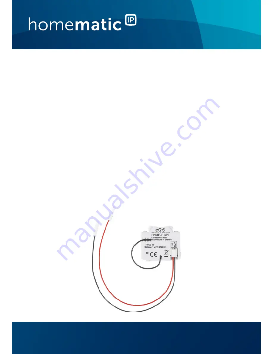
Kontakt-Schnittstelle Unterputz –1-fach
S. 2
Contact Interface flush-mount –1 channel
p. 24
HmIP-FCI1
Page 1: ...Installations und Bedienungsanleitung Installation instruction and operating manual Kontakt Schnittstelle Unterputz 1 fach S 2 Contact Interface flush mount 1 channel p 24 HmIP FCI1 ...
Page 2: ...nischer oder chemischer Verfahren verviel fältigt oder verarbeitet werden Es ist möglich dass die vorliegende Anleitung noch drucktech nische Mängel oder Druckfehler aufweist Die Angaben in dieser Anleitung werden jedoch regelmäßig überprüft und Korrekturen in der nächsten Ausgabe vorgenommen Für Fehler technischer oder drucktechnischer Art und ihre Folgen übernehmen wir keine Haftung Alle Warenze...
Page 3: ...1 E F B C A D ...
Page 4: ...2 3 ...
Page 5: ...4 5 CR2032 ...
Page 6: ...Inbetriebnahme 10 5 1 Installation 10 5 2 Anlernen 13 6 Batterie wechseln 14 7 Fehlerbehebung 16 7 1 Schwache Batterie 16 7 2 Befehl nicht bestätigt 16 7 3 Duty Cycle 17 7 4 Fehlercodes und Blinkfolgen 18 8 Wiederherstellung der Werkseinstellungen 20 9 Wartung und Reinigung 21 10 Allgemeine Hinweise zum Funkbetrieb 21 11 Technische Daten 22 ...
Page 7: ...te Symbole Achtung Hier wird auf eine Gefahr hingewiesen Hinweis Dieser Abschnitt enthält zusätzliche wichtige Informationen 2 Gefahrenhinweise Öffnen Sie das Gerät nicht Es enthält keine durch den Anwender zu wartenden Teile Im Fehlerfall lassen Sie das Gerät von einer Fachkraft prüfen Aus Sicherheits und Zulassungsgründen CE ist das eigenmächtige Umbauen und oder Verän dern des Geräts nicht gest...
Page 8: ...nder zu einem gefährlichen Spielzeug werden Bei Sach oder Personenschäden die durch un sachgemäße Handhabung oder Nichtbeachten der Gefahrenhinweise verursacht werden über nehmen wir keine Haftung In solchen Fällen er lischt jeder Gewährleistungsanspruch Für Folge schäden übernehmen wir keine Haftung Das Gerät ist nur für den Einsatz in wohnungs ähnlichen Umgebungen geeignet Jeder andere Einsatz a...
Page 9: ...el in einer Unterputzdose montiert werden Vorhandene Schalter oder Schalterserien lassen sich ohne zusätzlichen Montageaufwand weiternutzen Über die kostenlose Homematic IP Smartphone App können auch Schalter und Magnetkontakte mit der Kon takt Schnittstelle verknüpft werden um eine komfortable Kommunikation per Funk zu ermöglichen Die langlebige auswechselbare Lithium Batterie hat eine Lebensdaue...
Page 10: ...lösungen zu betreiben Welcher Funktionsumfang sich innerhalb des Systems im Zusammenspiel mit wei teren Komponenten ergibt entnehmen Sie bitte dem Homematic IP Anwenderhandbuch Alle technischen Dokumente und Updates finden Sie stets aktuell unter www eQ 3 de 5 Inbetriebnahme 5 1 Installation Sollten für die Montage bzw Installation des Gerätes Än derungen oder Arbeiten an der Hausinstallation erfo...
Page 11: ...en Erden und Kurzschließen benachbarte unter Spannung stehende Teile abdecken oder abschranken Auswahl des geeigneten Werkzeuges der Messgeräte und ggf der persönlichen Schutzausrüstung Auswertung der Messergebnisse Auswahl des Elektro Installationsmaterials zur Sicherstel lung der Abschaltbedingungen IP Schutzarten Einbau des Elektroinstallationsmaterials Art des Versorgungsnetzes TN System IT Sy...
Page 12: ...se verbaut werden sofern dort keine potentialführenden Leitungen liegen Die Anschlussleitungen des Tasters Schalters Kontakts dürfen nicht länger als drei Meter sein Es ist strikt darauf zu achten dass die Anschluss leitungen räumlich getrennt von netzspannungs führenden Leitungen verlegt werden z B in ei genen Kabelkanälen oder Installationsrohren Die Kontakt Schnittstelle ist nur für den Anschlu...
Page 13: ... integriert werden und mit anderen Homematic IP Geräten kommu nizieren kann muss sie zunächst an den Homematic IP Access Point angelernt werden Zum Anlernen der Kontakt Schnittstelle gehen Sie wie folgt vor Öffnen Sie die Homematic IP App auf Ihrem Smartphone Wählen Sie den Menüpunkt Gerät anlernen aus Schieben Sie den mit der Batterie bestückten mit gelieferten Batteriehalter C in das Batteriefac...
Page 14: ...leuchtet die LED A grün Das Gerät ist nun einsatzbereit Leuchtet die LED rot versuchen Sie es erneut Wählen Sie aus in welche Anwendung z B Licht und oder Beschattung das Gerät verwendet werden soll Vergeben Sie in der App einen Namen für das Ge rät und ordnen Sie es einem Raum zu 6 Batterie wechseln Schieben Sie den Batteriehalter nur mit eingeleg ter Batterie in das Gerät da er sich sonst nicht ...
Page 15: ...nbezeichnung auf der Batte rie nach oben zeigt s Abbildung 5 Die eingesetzte Lithium Knopfzelle muss kurz schlussfest sein Verwenden Sie zum Einlegen nur den mitgelieferten Batteriehalter und keine me tallischen Gegenstände wie z B eine Zange oder Pinzette Nach dem Einlegen der Batterie führt das Gerät zunächst einen Selbsttest für ca 2 Sekunden durch Danach erfolgt die Initialisierung Den Abschlu...
Page 16: ...ung kann evtl nach kur zer Erholungszeit der Batterie wieder mehrfach gesendet werden Bricht beim Senden die Spannung wieder zusammen wird dies in der Homematic IP App und am Gerät ange zeigt s 7 4 Fehlercodes und Blinkfolgen auf Seite 18 Tauschen Sie in diesem Fall die leere Batterie gegen eine neue aus s 6 Batterie wechseln auf Seite 14 7 2 Befehl nicht bestätigt Bestätigt mindestens ein Empfäng...
Page 17: ...ner Stunde also 36 Sekunden in einer Stunde Die Geräte dürfen bei Erreichen des 1 Limits nicht mehr senden bis diese zeitliche Begrenzung vorüber ist Gemäß dieser Richtlinie werden Homematic IP Geräte zu 100 nor menkonform entwickelt und produziert Im normalen Betrieb wird der Duty Cycle in der Regel nicht erreicht Dies kann jedoch in Einzelfällen bei der In betriebnahme oder Erstinstallation eine...
Page 18: ...den soll Blinkcode Bedeutung Lösung Kurzes oranges Blinken Funkübertra gung Sen deversuch Datenübertra gung Warten Sie bis die Übertragung been det ist 1x langes grünes Leuchten Vorgang bestätigt Sie können mit der Bedienung fortfah ren 1x langes rotes Leuchten Vorgang fehlgeschla gen oder Duty Cycle Limit erreicht Versuchen Sie es erneut 7 2 Befehl nicht bestätigt auf Seite 16 oder 7 3 Duty Cycle...
Page 19: ...n alle 10 s Anlernmodus aktiv Geben Sie die letz ten vier Ziffern der Geräte Seriennum mer zur Bestätigung ein s 5 2 Anlernen auf Seite 13 6x langes rotes Blinken Gerät defekt Achten Sie auf die Anzeige in Ihrer App oder wenden Sie sich an Ihren Fachhändler 1x oranges und 1x grünes Leuchten nach dem Einlegen der Batterien Testanzeige Nachdem die Test anzeige erloschen ist können Sie fortfahren ...
Page 20: ...n Sie das Batteriefach B indem Sie den Batteriehalter C herausziehen s Abbildung 3 Setzen Sie den Batteriehalter wieder ein und hal ten Sie gleichzeitig die Systemtaste A für 4 s ge drückt bis die LED A schnell orange zu blinken beginnt s Abbildung 4 Lassen Sie die Systemtaste wieder los Drücken Sie die Systemtaste erneut für 4 s bis die LED grün aufleuchtet Lassen Sie die Systemtaste wieder los u...
Page 21: ...iffen werden 10 Allgemeine Hinweise zum Funkbetrieb Die Funk Übertragung wird auf einem nicht exklusiven Übertragungsweg realisiert weshalb Störungen nicht ausgeschlossen werden können Weitere Störeinflüsse können hervorgerufen werden durch Schaltvorgänge Elektromotoren oder defekte Elektrogeräte Die Reichweite in Gebäuden kann stark von der im Freifeld abweichen Außer der Sendeleistung und den Em...
Page 22: ...Geräte Kurzbezeichnung HmIP FCI1 Versorgungsspannung 1x 3 V CR2032 Stromaufnahme 30 mA max Batterielebensdauer 2 Jahre typ Schutzart IP20 Umgebungstemperatur 5 bis 35 C Abmessungen B x H x T 41 x 12 x 35 mm Gewicht 14 5 g inkl Batterie Funk Frequenzband 868 0 868 6 MHz 869 4 869 65 MHz Maximale Funk Sendeleistung 10 dBm Empfängerkategorie SRD category 2 Typ Funk Freifeldreichweite 280 m Duty Cycle...
Page 23: ...ktro und Elektronik Altgeräte über die örtlichen Sammelstellen für Elektronik Altgeräte zu entsorgen Konformitätshinweis Das CE Zeichen ist ein Freiverkehrszeichen das sich ausschließlich an die Behörden wendet und keine Zusicherung von Eigenschaften beinhaltet Bei technischen Fragen zum Gerät wenden Sie sich bitte an Ihren Fachhändler ...
Page 24: ... electronic mechanical or chemical means without the written consent of the publisher Typographical and printing errors cannot be excluded However the information contained in this manual is reviewed on a regular basis and any necessary corrections will be implemented in the next edition We accept no liability for technical or typographical errors or the consequences thereof All trademarks and ind...
Page 25: ...5 Start up 29 5 1 Installation 29 5 2 Teaching in 32 6 Changing the battery 33 7 Troubleshooting 35 7 1 Weak battery 35 7 2 Command not confirmed 35 7 3 Duty Cycle 36 7 4 Error codes and flashing sequences 37 8 Restore factory settings 38 9 Maintenance and cleaning 39 10 General information about radio operation 39 11 Technical specifications 40 ...
Page 26: ...o other persons for use please hand over this manual as well Symbols used Attention This indicates a hazard Please note This section contains important ad ditional information 2 Hazard information Do not open the device It does not contain any parts that can be maintained by the user In the event of an error please have the device checked by an expert For safety and licensing reasons CE unautho ri...
Page 27: ...lms bags and pie ces of polystyrene can be dangerous in the hands of a child We do not assume any liability for damage to pro perty or personal injury caused by improper use or the failure to observe the hazard information In such cases any claim under warranty will be invalidated We assume no liability for conse quential damages The device may only be operated within residen tial buildings Using ...
Page 28: ...act interface can be mounted flexibly inside a flush mounted box Existing switches or switch series can continue to be used without any additional installation effort The free Homematic IP smartphone app even allows switches and magnetic contacts to be connected to the contact interface to facilitate convenient wireless com munication The durable replaceable lithium battery has a service life of u...
Page 29: ...tner solutions The available func tions provided by the system in combination with other components are described in the Homematic IP User Guide All current technical documents and updates are provided at www eQ 3 com 5 Start up 5 1 Installation If changes or works have to be made on the house instal lation for mounting or installing the device the following safety instruction must be considered P...
Page 30: ...ircuit cover or cordon off neighbouring live parts Select a suitable tool measuring equipment and if necessary personal safety equipment Evaluate measuring results Select electrical installation material for safeguarding shut off conditions IP protection types Install electrical installation material Type of supply network TN system IT system TT system and the resulting connecting conditions such ...
Page 31: ... live wires The connecting cables for the pushbutton switch contact must not be longer than three metres It is absolutely essential to ensure that the connec ting cables are laid so that they are physically sepa rate from cables carrying mains voltage for ex ample in separate cable ducts or wiring conduits The contact interface is only suitable for connec ting floating pushbuttons Do not connect t...
Page 32: ...our system and enable it to communicate with other Homematic IP de vices you must teach in the device to your Homematic IP Access Point first To teach in the contact interface please proceed as fol lows Open the Homematic IP app on your smartphone Select the menu item Teach in device Slide the supplied battery holder C containing the battery into the battery compartment B of the device see Figure ...
Page 33: ...please try again Please select the application for example light and or security in which the device will be used In the app give the device a name and allocate it to a room 6 Changing the battery Only slide the battery holder into the device if it contains a battery otherwise it can no longer be removed If the app or device displays an empty battery see Section 7 4 Error codes and flashing sequen...
Page 34: ... inserted the device starts by per forming a self test for approx 2 seconds Afterwards initia lisation is carried out The LED test display will indicate that initialisation is complete by lighting up orange and green Caution There is a risk of explosion if the battery is not replaced correctly Only replace with the same or equivalent type Never recharge standard batteries Do not throw the batterie...
Page 35: ...ia the Homematic IP app see Section 7 4 Error codes and flashing sequences on page 37 In this case replace the empty battery with a new one see Section 6 Changing the battery on page 33 7 2 Command not confirmed If at least one receiver does not confirm a command the device LED E lights up red at the end of the failed trans mission process The failed transmission may be caused by radio interferenc...
Page 36: ...reach the 1 limit until this time restriction comes to an end Homematic IP devices are designed and produced with 100 conformity to this regulation During normal operation the duty cycle is not usually reached However repeated and radio intensive teach in processes mean that it may be reached in isolated in stances during start up or initial installation of a system If the duty cycle is exceeded t...
Page 37: ...t orange flashing Radio trans mission attempting to transmit data transmission Wait until the transmission is completed 1x long green light Transmission confirmed You can continue operation 1x long red light Transmission failed or duty cycle limit is reached Try again 7 2 Com mand not confir med on page 35 or 7 3 Duty Cycle on page 36 Short orange light after green or red confirmation Battery empt...
Page 38: ...ange and 1x green light after inserting batteries Test display Once the test display has stopped you can continue 8 Restore factory settings The factory settings of the device can be resto red If you do this you will lose all your settings To restore the factory settings of the contact interface please proceed as follows Open the battery compartment B by pulling out the battery holder C see Figure...
Page 39: ...intenance other than replacing the battery when necessary Enlist the help of an expert to carry out any repairs Clean the device using a soft lint free cloth that is clean and dry Do not use any detergents containing solvents as they could corrode the plastic housing and label 10 General information about radio operation Radio transmission is performed on a non exclusive transmission path which me...
Page 40: ...eer Germany declares that the radio equipment type Homematic IP HmIP FCI1 is in compliance with Directive 2014 53 EU The full text of the EU declaration of conformity is available at the following internet address www eq 3 com 11 Technical specifications Device short description HmIP FCI1 Supply voltage 1x 3 V CR2032 Current consumption 30 mA max Battery life 2 years typ Degree of protection IP20 ...
Page 41: ...regular domes tic waste Electronic equipment must be dis posed of at local collection points for waste elec tronic equipment in compliance with the Waste Electrical and Electronic Equipment Directive Information about conformity The CE sign is a free trading sign addressed ex clusively to the authorities and does not include any warranty of any properties For technical support please contact your ...
Page 42: ...lmächtigter des Herstellers Manufacturer s authorised representative eQ 3 AG Maiburger Straße 29 26789 Leer GERMANY www eQ 3 de Kostenloser Download der Homematic IP App Free download of the Homematic IP app ...