
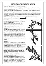
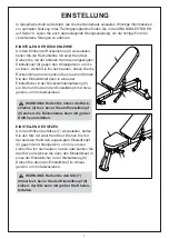


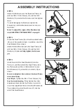
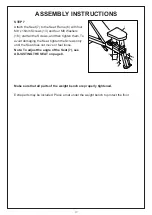


STEP 4
Attach the Backrest (4) to the Backrest Frame (3)
with four M8 x 15mm Screws (13) and four M8
Washers (18); start all the Screws, and then tighten
them.
To avoid damaging the Backrest, tighten the
Screws only until the Backrest does not move or
feel loose.
Note: To adjust the angle of the Backrest (4),
see ADJUSTING THE BACKREST on page 8.
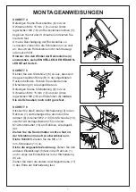
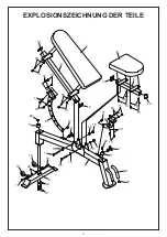
STEP 5
Orient the Seat Frame (6) so that the welded tubes
(B) are in the position shown. In addition, orient the
Seat Bracket (8) as shown.
Attach the Seat Bracket (8) to the Seat Frame (6)
with four M8 x 15mm Screws (13) and four M8
Washers (18);
do not fully tighten the Screws
yet.
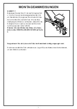
STEP 6
Insert the end of the Seat Bracket (8) into the
Frame (1), and then attach the Seat Frame (6) to
the Frame with an M12 x 100mm Bolt (14), two
M12 Washers (15), and an M12 Locknut (16) as
shown.
Do not overtighten the Locknut; the Seat Frame
must pivot freely.
See Step 6.
Tighten the M8 x 15mm Screws (13).
See the inset drawing.
Firmly tighten the other
Adjustment Knob (9) into the Frame (1) and into
one of the adjustment holes in the Seat Bracket (8).
Then, tighten the other Stop Screw (17) into the
end of the Seat Bracket.
13
18
4
3
13
18
1318
13
18
18
18
13
8
6
B
13
15
14
15
16
8
1
6
17
9
8
1
ASSEMBLY INSTRUCTIONS
18
Summary of Contents for A91-179
Page 24: ......