
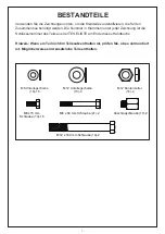

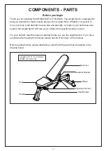


A. Assembly requires two persons.
B. Because of its weight and size, assemble the weight bench in the location there it will
be used. Make sure that there is enough clearance to walk around the weight bench as
you assemble it.
C. Place all parts in a cleared area and remove the packing materials. Do not dispose of
the packing materials until you finish all assembly steps.
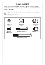
D. In addition to the included tool(s), assembly requires the following tools:
two adjustable wrenches
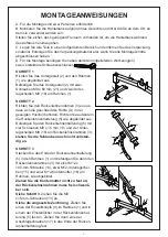
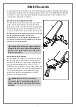
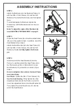
STEP 2
Orient the Backrest Frame (3) so that the welded
tubes (A) are in the position shown. In addition,
orient the Backrest Bracket (5) as shown.
Attach the Backrest Bracket (5) to the Backrest
Frame (3) with four M8 x 15mm Screws (13) and
four M8 Washers (18);
do not fully tighten the
Screws yet.
STEP 1
Orient the Base (2) and the Frame (1) as shown.
Attach the Base (2) to the Frame (1) with two M8 x
60mm Screws (21) and two M8 Washers (18).
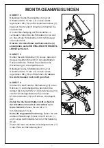
STEP 3
Insert the end of the Backrest Bracket (5) into the
Frame (1), and then attach the Backrest Frame (3)
to the Frame with an M12 x 100mm Bolt (14), two
M12 Washers (15), and an M12 Locknut (16) as
shown.
Do not overtighten the Locknut; the Backrest
Frame must pivot freely.
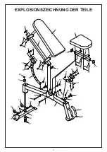
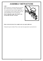
See step 3.
Tighten the M8 x 15mm Screws (13).
See the inset drawing.
Firmly tighten one of the
Adjustment Knobs (9) into the Frame (1) and into
one of the adjustment holes in the Backrest Bracket
(5). Then, tighten one of the Stop Screws (17) into
the end of the Backrest Bracket.
2
1
21
18
13
13
18
18
18
18
5
A
3
15
14
15 16
5
1
3
17
9
1
5
ASSEMBLY INSTRUCTIONS
17
Summary of Contents for A91-179
Page 24: ......