


Rev. 1.00
495 of 576
January 28, 2022
32-Bit Arm
®
Cortex
®
-M0+ MCU
HT32F54231/HT32F54241/HT32F54243/HT32F54253
23 Universal
Asynchronous Receiver T
ransmitter (UART)
23 Universal
Asynchronous Receiver T
ransmitter (UART)
Features
▆
Supports asynchronous serial communication modes
▆
Full Duplex Communication Capability
▆
Programming baud rate clock frequency up to (f
PCLK
/16) MHz
▆
Fully programmable serial communication functions including:
●
Word length: 7, 8 or 9-bit character
●
Parity: Even, odd or no-parity bit generation and detection
●
Stop bit: 1 or 2 stop bits generation
●
Bit order: LSB-first or MSB-first transfer
▆
Error detection: Parity, overrun, and frame error
▆
Supports PDMA Interface, the PDMA related describes are only available for the HT32F54243/
HT32F54253 devices
Functional Descriptions
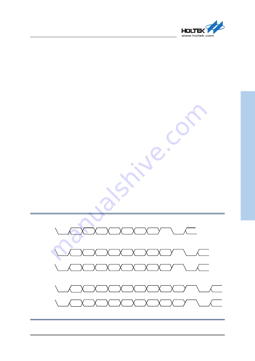
Serial Data Format
The UART module performs a parallel-to-serial conversion on data that is written to the transmit
data register and then sends the data with the following format: Start bit, 7 ~ 9 LSB/MSB first data
bits, optional Parity bit and finally 1 ~ 2 Stop bits. The Start bit has the opposite polarity of the
data line idle state. The Stop bit is the same as the data line idle state and provides a delay before
the next start situation. Both the Start and Stop bits are used for data synchronization during the
asynchronous data transmission.
The UART module also performs a serial-to-parallel conversion on the data that is read from the
receive data register. It will first check the Parity bit and will then look for a Stop bit. If the Stop bit
is not found, the UART module will consider the entire word transmission as failed and respond
with a Framing Error.
Start Bit
Start Bit
Stop Bit
Stop Bit
Next Start
Bit
Next Start
Bit
Bit0
Bit1
Bit2
Bit3
Bit4
Bit5
Bit6
Bit0
Bit1
Bit2
Bit3
Bit4
Bit5
Bit6
Bit7
Bit8
8-Bit Data Format
9-Bit Data Format
Parity Bit
Start Bit
Bit0
Bit1
Bit2
Bit3
Bit4
Bit5
Bit6
7-Bit Data Format
Stop Bit
Next Start
Bit
Start Bit
Stop Bit
Next Start
Bit
Bit0
Bit1
Bit2
Bit3
Bit4
Bit5
Bit6
Bit7
Start Bit
Stop Bit
Next Start
Bit
Bit0
Bit1
Bit2
Bit3
Bit4
Bit5
Bit6
Bit7 Parity Bit
(WLS[1:0]=b00, PBE=0)
(WLS[1:0]=b01, PBE=0)
(WLS[1:0]=b00, PBE=1)
(WLS[1:0]=b10, PBE=0)
(WLS[1:0]=b01, PBE=1)
Figure 181. UART Serial Data Format