


Rev. 1.00
477 of 576
January 28, 2022
32-Bit Arm
®
Cortex
®
-M0+ MCU
HT32F54231/HT32F54241/HT32F54243/HT32F54253
22 Universal Synchronous
Asynchronous Receiver T
ransmitter (USART)
22 Universal Synchronous
Asynchronous Receiver T
ransmitter (USART)
RS485 Auto Address Detection Operation Mode – AAD
Except in the Normal Multi-drop Operation Mode, the RS485 mode can operate in the Auto
Address Detection Operation Mode, AAD, when it is configured as an addressable slave. This
mode is enabled by setting the RSAAD field to 1 in the RS485CR register. The receiver will
detect the address frame with a parity bit “1” and then compare the received address data with the
ADDMATCH field value which is a programmable 8-bit address value specified in the RS485CR
register. If the address data matches the ADDMATCH value, it will be stored in the RX FIFO and
the URRXEN bit will be automatically set. When the receiver is enabled, all received data will be
stored in the RX FIFO until the next address frame does not match the ADDMATCH value and
then the receiver will be automatically disabled. After the receiver is enabled, software can disable
the receiver by clearing the URRXEN bit to ‘0’.
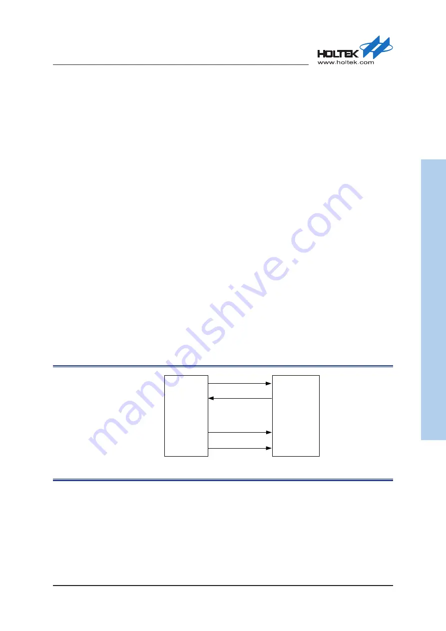
Synchronous Master Mode
The data is transmitted in a full-duplex style in the USART Synchronous Master Mode, i.e.,
data transmission and reception both occur at the same time and only support master mode. The
USART CTS pin is the synchronous USART transmitter clock output. In this mode, no clock
pulses will be sent to the CTS pin during the start bit, parity bit and stop bit duration. The CPS bit
in the Synchronous Control Register SYNCR, can be used to determine whether data is captured
on the first or the second clock edge. The CPO bit in the SYNCR can be used to configure the clock
polarity in the USART Synchronous Mode idle state. Detailed timing information is shown in the
Figure 220.
In the USART synchronous Mode, the USART CTS/SCK clock output pin is only used to transmit
the data to slave device. If the transmission data register USRDR, is written with valid data, the
USART synchronous mode will automatically transmit this data with the corresponding clock
output and the USART receiver will also receive data on the RX pin. Otherwise the receiver will
not obtain synchronous data if no data is transmitted.
USART
(Master)
Device
(Slave)
TX
RX
Data in
Data out
CTS/SCK
Clock
GPIO for Chip Select
CS
Figure 178. USART Synchronous Transmission Example
Note:
The USART supports the synchronous master mode only: it cannot receive or send data related
to an input clock. The USART CTS/SCK clock is always an output.