


Rev. 1.00
473 of 576
January 28, 2022
32-Bit Arm
®
Cortex
®
-M0+ MCU
HT32F54231/HT32F54241/HT32F54243/HT32F54253
22 Universal Synchronous
Asynchronous Receiver T
ransmitter (USART)
22 Universal Synchronous
Asynchronous Receiver T
ransmitter (USART)
When the USART CTS pin is forced to a logic high state during a data transmission period, the
current data transmission will be continued until the stop bit is completed. The following figure
shows an example of communication with CTS flow control.
Start Bit
Bit 0 Bit 1 Bit 2 Bit 3 Bit 4
Bit N
Parity Bit
Stop Bit
Start Bit
N = 7 ~ 8
Idle
Bit 0
Bit 1 Bit 2 Bit 3 Bit 4
Bit N
Parity Bit
Stop
Bit
N = 7 ~ 8
TXFS[3:0]
4
3
2
CTS
Start Bit
Bit 0
Figure 174. USART CTS Flow Control
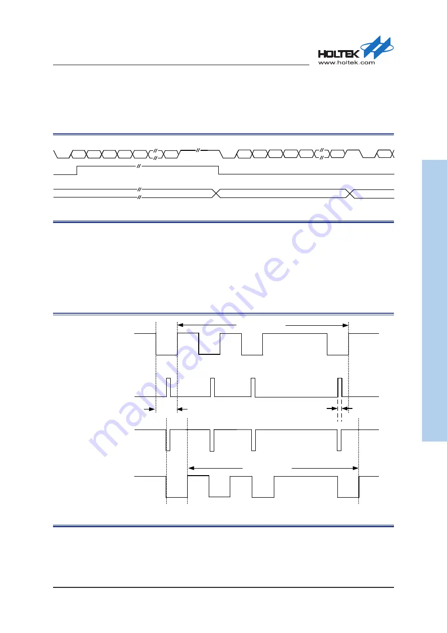
IrDA
The USART IrDA mode is provided for half-duplex point-to-point wireless communication.
The USART module includes an integrated modulator and demodulator which allow a wireless
communication using infrared transceivers. The transmitter specifies a logic data ‘0’ as a ‘high’
pulse and a logic data ‘1’ as a ‘low’ level while the Receiver specifies a logic data ‘0’ as a ‘low’
pulse and a logic data ‘1’ as ‘high’ level in the IrDA mode.
1
0
0
1
1
0
1
1
1
0
START
TX_Data
IrDA TX
Modulation
Signal
STOP
3/16 bit width
RX_Data
bit width
1
0
0
1
1
0
1
1
1
0
START
STOP
Data Frame
Data Frame
IrDA RX
Demodulation
Signal
Figure 175. IrDA Modulation and Demodulation
The IrDA mode provides two operation modes, one is the normal mode, and the other is the low-
power mode.