


Rev. 1.00
244 of 576
January 28, 2022
32-Bit Arm
®
Cortex
®
-M0+ MCU
HT32F54231/HT32F54241/HT32F54243/HT32F54253
14 General-Purpose T
imer (GPTM)
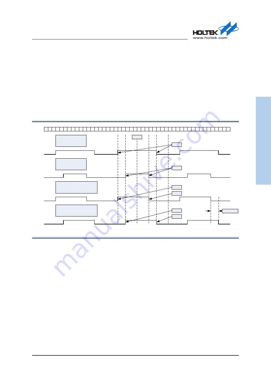
Asymmetric PWM Mode
Asymmetric PWM mode allows two center-aligned PWM signals to be generated with a
programmable phase shift. While the PWM frequency is determined by the value of the CRR
register, the duty cycle and the phase-shift are determined by the CHxCCR and CHxACR register.
When the counter is counting up, the PWM uses the value in CHxCCR as up-count compare value.
When the counter is into counting down stage, the PWM uses the value in CHxACR as down-
count compare value. The following figure is shown as an example for asymmetric PWM mode in
center-aligned counting mode.
Note: Asymmetric PWM mode can only be operated in center-aligned counting mode.
2 3 4 5 6 7
0 1
8
5 4 3 2 1 0
7 6
2 3 4 5 6 7
1
8
5 4 3 2 1 0
7 6
2 3 4 5 6 7
1
8
5 4 3 2 1
7 6
CNTR
CHxOREF
CHxOREF
CHxOREF
CHxOREF
PWM center-aligned mode
CRR = 8
CCR = 3, ACR = X
PWM center-aligned mode
CRR = 8
CCR = 5, ACR = X
Asymmetric PWM center-aligned mode
CRR = 8
CCR = 3, ACR = 5
Asymmetric PWM center-aligned mode
CRR = 8
CCR = 5, ACR = 3
CCR = 3
CCR = 5
CCR = 3
ACR = 5
CCR = 5
ACR = 3
Phase delay = 2
CRR = 8
Figure 68. Asymmetric PWM Mode versus Center-Aligned Counting Mode
Timer Interconnection
The timers can be internally connected together for timer chaining or synchronization. This can
be implemented by configuring one timer to operate in the Master mode while configuring another
timer to be in the Slave mode. The following figures present several examples of trigger selection
for the master and slave modes.
Using One Timer to Enable/Disable another Timer Start or Stop Counting
▆
Configure GPTM as the master mode to send its channel 0 Output Reference signal CH0OREF
as a trigger output (MMSEL = 0x4).
▆
Configure GPTM CH0OREF waveform.
▆
Configure PWM0 to receive its input trigger source from the GPTM trigger output (TRSEL = 0xA).
▆
Configure PWM0 to operate in the pause mode (SMSEL = 0x5).
▆
Enable PWM0 by writing ‘1’ to the TME bit.
▆
Enable GPTM by writing ‘1’ to the TME bit.