


Rev. 1.00
191 of 576
January 28, 2022
32-Bit Arm
®
Cortex
®
-M0+ MCU
HT32F54231/HT32F54241/HT32F54243/HT32F54253
12
Analog to Digital Converter (ADC)
12
Analog to Digital Converter (ADC)
CH2
Cycle
Start of
Conversion
CH4
CH7
CH5
CH6
CH3
CH0
CH1
Conversion
Single sample
End of
Conversion
(ex: Sequence Length=8)
Cycle End of
Conversion
CH2
CH4
CH7
CH5
CH6
Cycle
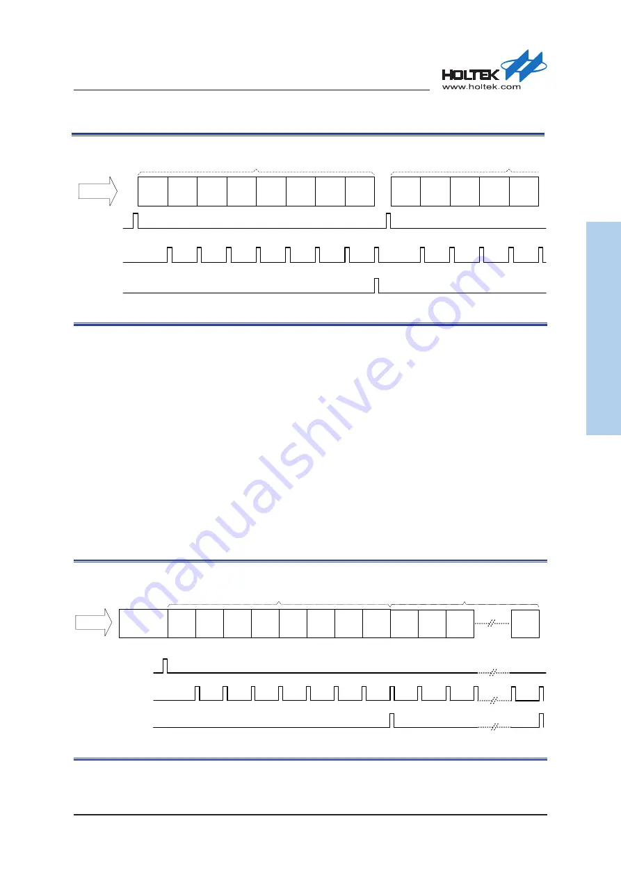
Figure 31. One Shot Conversion Mode
Continuous Conversion Mode
In the Continuous Conversion Mode, repeated conversion cycle will restart automatically without
requiring additional A/D start trigger signals after a channel group conversion has completed.
When the A/D conversion mode field ADMODE[1:0] is set to 0x2, the A/D converter will operate
in the Continuous Conversion Mode which can be started by a software trigger, a comparator
output transition event, an external EXTI event or a TM event determined by the Trigger Control
Register ADCTCR and the Trigger Source Register ADCTSR.
After conversion:
▆
The converted data will be stored in the 16-bit ADCDRy (y = 0 ~ 7) registers.
▆
The ADC group cycle end of conversion event raw status flag, ADIRAWC, in the ADCIRAW
register will be set when the conversion cycle is finished.
▆
An interrupt will be generated after a group cycle end of conversion if the ADIEC bit in the
ADCIER register is enabled.
Continuous Conversion Mode
(ex: Sequence Length=8)
CH2
Cycle
Start of Conversion
CH4
CH7
CH5
CH6
CH3
CH0
CH1
Cycle End of Conversion
Single sample End of
Conversion
Idle
CH2
Cycle
CH4
CH7
CH1
Figure 32. Continuous Conversion Mode