
Document No: C-61-00003-3
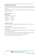
3.15 Ethernet communication
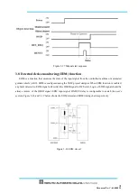
Measurement data of UAM can be obtained from the Ethernet communication. Water proof Ethernet
connector is located at the back of UAM. To connect sensor with PC use an Optional Ethernet cable
(UAM-ENET).
UAM is compatible with SCIP2.2 communication protocol standard. Refer to UAM-05LP communication
specification (C-64-00012).
3.15.1 Ethernet Setting
●
Default setting
Factory default value is shown below.
IP address : 192.168.0.10
Default gateway : 192.168.0.1
Subnet mask : 255.255.255.0
Port number : 10940
●
Changing the IP address
IP address can be changed by using UAM project Designer. Refer to section 7.13 and 7.9.1 for details.
●
IP address initialization
Ethernet settings can be set to factory default by using IP initialization switch.
<Initialization steps>
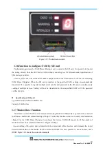
a) Prepare a thin strong pin for IP initialization process. IP initialization switch is located exactly below the
SD card Slot (Refer to figure 3-27)
b) When UAM is operating in normal state, press and hold the IP initialization switch for more than 3
seconds. After initialization process is complete 7-segment display status changes to “Fb”.
c) Sensor restarts with 7-segment display showing the status “00”.
Summary of Contents for UAM-05LP
Page 1: ... Document No C 61 00003 3 ...
Page 104: ... Document No C 61 00003 3 Figure 7 33 b Function Figure7 33 c Area ...
Page 107: ... Document No C 61 00003 3 Figure 7 36 a Project report tab Figure 7 36 b Error report tab ...
Page 148: ... Document No C 61 00003 3 13 External dimension 13 1 UAM 05LP ...
Page 149: ... Document No C 61 00003 3 13 2 Base mounting bracket ...
Page 150: ... Document No C 61 00003 3 13 3 Rear mounting bracket ...
Page 151: ... Document No C 61 00003 3 13 4 Cover Protection Bracket ...
Page 152: ... Document No C 61 00003 3 14 EC Declaration of conformity ...
Page 153: ... Document No C 61 00003 3 ...


