
Document No: C-61-00003-3
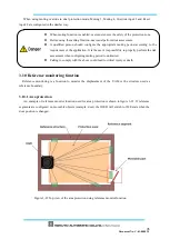
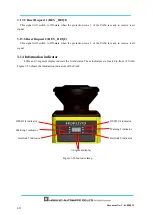
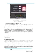
3.14.1 LED
LED indicators and their descriptions are shown in Table 3-5.
Table 3-5 Description of indicator LEDs
LED
Color
Description
OSSD 1/2
Green/Red
Green LED when OSSD 1/2 signal is in ON state,
Red LED when OSSD 1/2 signal OFF state
OSSD 3/4
Green/Red
Green LED when OSSD 3/4 signal is in ON state,
Red LED when OSSD 3/4 signal OFF state
Green LED when OSSD 3/4 signal is not in use
WARNING 1
Orange
LED ON when Warning 1 signal is in OFF state
LED OFF when Warning 1 signal is not in use
WARNING 2
Orange
LED ON when Warning 2 signal is in OFF state
LED OFF when Warning 2 signal is not in use
Interlock 1
Orange
LED ON when OSSD 1/ 2 is in interlock state
Interlock 2
Orange
LED ON when OSSD 3/ 4 is in interlock state
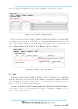
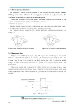
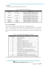
3.14.2 7-Segment display
Table 3-6 shows the descriptions of the numbers shown 7 segment display of UAM.
Numbers can be displayed upside-down by enabling the 7-segment display function on the configuration
software “UAM Project Designer”. This will help to read the numbers with ease when the device has to be
inverted for the mounting. Dots on the 7-segment will illuminate when the upside-down display function is
active.
Table 3-6
Description of numbers displayed on 7-segment
Display number
Details
00
Sensor is initializing
01 – 32
Selected Area 1 to 32
33
Setting mode
34
Interlock state (Protection zone 1
)
35
Interlock state (Protection zone 2)
36
Interlock state (Both protection zone 1and 2)
37
Muting or Override state (Protection zone 1
)
38
Muting or Override state (Protection zone 2)
39
Muting or Override state (Both protection zone 1 and 2)
40
Laser Off mode
F2
SD card is detected with correct configuration file
F3
Configuring the sensor from the SD card information
F4
Configuring from the SD card is successful. Remove the SD
card to complete the process.
F5
SD card process is complete. Sensor is going to restart.
Fb
Reset of IP address is complete. Sensor is going to restart.
Note: Display numbers other than the above are error state. For details refer to table 9-2 for details (
page 133
)
.
Summary of Contents for UAM-05LP
Page 1: ... Document No C 61 00003 3 ...
Page 104: ... Document No C 61 00003 3 Figure 7 33 b Function Figure7 33 c Area ...
Page 107: ... Document No C 61 00003 3 Figure 7 36 a Project report tab Figure 7 36 b Error report tab ...
Page 148: ... Document No C 61 00003 3 13 External dimension 13 1 UAM 05LP ...
Page 149: ... Document No C 61 00003 3 13 2 Base mounting bracket ...
Page 150: ... Document No C 61 00003 3 13 3 Rear mounting bracket ...
Page 151: ... Document No C 61 00003 3 13 4 Cover Protection Bracket ...
Page 152: ... Document No C 61 00003 3 14 EC Declaration of conformity ...
Page 153: ... Document No C 61 00003 3 ...


