
Document No: C-61-00003-3
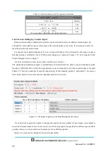
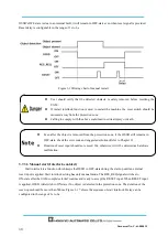
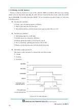
3. 13.5 Reset Request 1 (RES _ REQ1)
This signal will switch to ON-state when the protection zone 1 of the UAM is ready to receive reset
signal.
3.13.6 Reset Request 2 (RES _ REQ2)
This signal will switch to ON-state when the protection zone 2 of the UAM is ready to receive reset
signal.
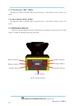
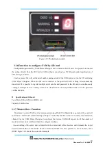
3.14 Information indicator
LEDs and 7-segment
display indicate
the UAM status. These indicators are located in front of UAM.
Figure 3-26 shows the information indicators of the UAM.
Figure 3-26 Indicator lamp
7-Segment display
OSSD 1/2 indicator
Warning 1 indicator
Interlock 1 indicator
OSSD 3/4 indicator
Warning 2 indicator
Interlock 2 indicator
Summary of Contents for UAM-05LP
Page 1: ... Document No C 61 00003 3 ...
Page 104: ... Document No C 61 00003 3 Figure 7 33 b Function Figure7 33 c Area ...
Page 107: ... Document No C 61 00003 3 Figure 7 36 a Project report tab Figure 7 36 b Error report tab ...
Page 148: ... Document No C 61 00003 3 13 External dimension 13 1 UAM 05LP ...
Page 149: ... Document No C 61 00003 3 13 2 Base mounting bracket ...
Page 150: ... Document No C 61 00003 3 13 3 Rear mounting bracket ...
Page 151: ... Document No C 61 00003 3 13 4 Cover Protection Bracket ...
Page 152: ... Document No C 61 00003 3 14 EC Declaration of conformity ...
Page 153: ... Document No C 61 00003 3 ...


