


20
SK3000 Systems
between the engine and fuel tank.
12-volt power is distributed to the 12-volt pumps
and strobe light through individual circuits that
are protected by in-line fuses near each battery.
Other fuses, located in the engine control panel
protect the engine control circuits. Most 12-volt
accessories are operated directly by switches in
the engine control panel or the waste dump con-
trol. The waterblasting tractor is equipped with
an independent, onboard electrical system.
The DC electrical system on your equipment is
designed for wet cell, industrial engine starting
batteries. Do not attempt to use gel cell, absorbed
wet mat or other non wet cell batteries. The en-
gine charging system is not designed to recharge
these batteries which could cause unusually short
battery life, engine starting problems and damage
to the charging system. You also should not mix
the size or brand of wet cell batteries. Always
consult Hog Technologies or the engine manu-
facturer before changing the type of batteries in
your SK3000.
Refer to the engine information manual for more
information on battery specifications, the en
-
gine electrical system and control panel on your
SK3000. Contact Hog Technologies Customer
Service if you need assistance correcting a prob-
lem with the electrical system.
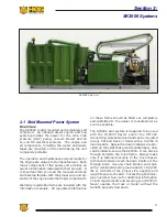
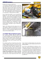
2.6 SK3000 Onboard Hydraulic System
Two hydraulic cylinders raise the waste tank
door and simultaneously extend the waste liner
to dump solid debris. A self contained hydraulic
power unit with onboard control solenoids, hy-
draulic oil reservoir and 12-Volt DC hydraulic pump
provides hydraulic oil pressure to the cylinders.
The hydraulic power unit is located on top of the
waste tank.
The hydraulic system is powered by the engine
12-Volt electrical system and controlled by mo-
mentary, Up/Down switches in a remote control.
To activate the dumping system, plug the cord
for the remote control into the receptacle near
the engine control panel. Make sure you and all
other personnel stay well clear of the unit while
dumping. Press and hold the white UP switch un-
til the debris is dumped or full travel is reached.
Release the switch to stop cylinders. Press and
hold the black DOWN switch to retract the liner
and lower door. Release the switch immediately
when the liner is fully retracted and the door is
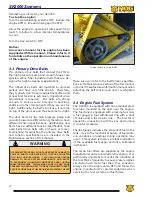
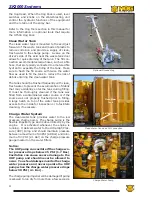
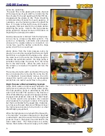
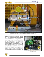
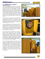
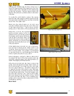
Electro Hydraulic Pump Unit and Air Compressor
on Top of The Waste Tank
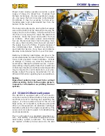
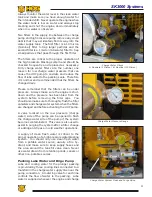
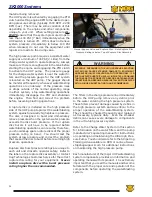
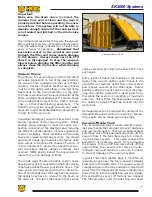
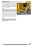
Hydraulic Cylinder Inside Waste Tank
closed. Refer to dumping debris in the waste tank
section of this manual for detailed instructions for
dumping debris.
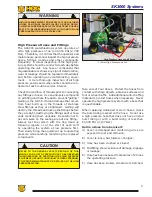
The oil level in the hydraulic oil reservoir on the
power unit should be checked periodically and
oil added as necessary. The full level is 1/4” to
1/2” from the bottom of the fill plug threads with
the waste tank door closed. Always use the type
of oil recommended by the hydraulic power unit
manufacturer when adding oil to the reservoir.
Refer to the Lubrication Chart in this manual and
the power unit operating manual for hydraulic oil
specifications.
Summary of Contents for Stripe Hog SK3000
Page 1: ...3 K Operations Manual...
Page 2: ...2...
Page 14: ...14 THIS PAGE WAS LEFT BLANK INTENTIONALLY...
Page 62: ...62 THIS PAGE WAS LEFT BLANK INTENTIONALLY...
Page 77: ...77 Component Repair HOG TECHNOLOGIES...
Page 79: ...79 Component Repair HOG TECHNOLOGIES...
Page 81: ...81 Component Repair HOG TECHNOLOGIES...
Page 82: ...82 NOTES...
Page 83: ...83 JETSTREAM UHP PUMP FLUID END Drawings and Schematics Appendix A HOG TECHNOLOGIES...
Page 86: ...86 THIS PAGE WAS LEFT BLANK INTENTIONALLY...
Page 90: ...90 THIS PAGE WAS LEFT BLANK INTENTIONALLY...
Page 92: ...92 THIS PAGE WAS LEFT BLANK INTENTIONALLY...
Page 104: ...104 THIS PAGE WAS LEFT BLANK INTENTIONALLY...
Page 107: ...107...


