- 22 -
6.7 CHANGING THE BATTERIES
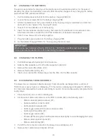
The person responsible for carrying out the maintenance should decide whether, for the sake of
simplicity, the entire internal battery pack with PCB should be changed. If only changing the battery
pack without PCB, proceed as follows:
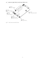
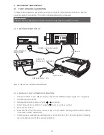
1. Pull the battery pack cable (F8) from the battery charging PCB (F3).
2. Loosen the two screws (F2) on the battery charging PCB.
3. Lift the clip fasteners at the top and bottom of the housing using a screwdriver or similar tool
and push the two halves of the housing (F1) apart.
4. Take both of the batteries out of the housing.
5. Insert the new batteries into the housing. Take care that the batteries on one side are some-
what raised and are correctly fitted and that cables are not trapped or squeezed.
6. Push the two halves of the housing together.
7. Plug the battery pack cable onto the battery charging PCB.
8. Fix the battery charging PCB to the housing using the two screws.
9. Montier
10. Führen Sie einen Akkutest durch (siehe ).
When using new batteries without a PCB (art. no. 1600 0015), a battery test must be per-
formed (see section section 8.4) after assembling the device.
6.8 CHANGING THE FILTERS
1.
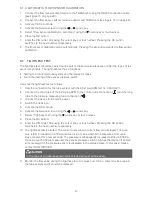
Pull the filter cassette holder (D3) from the device.
2.
Slide the filter cassette out from the filter cassette holder (D4).
3.
Remove the coarse filter (black, D10).
4.
Remove the fine filter (white, G7).
5.
Insert a new coarse filter, followed by a new fine filter, into the filter cassette.
6.9 EXCHANGING THE BLOWER BOX
The blower box is contained in Maintenance kit 5 and should be exchanged after a runtime of
15000 hours or every 5 years or displaying in the device or displaying via bargraph in VENTcon-
trol. Open and disassemble the device according to section 6.2 and subsequently complete the fol-
lowing steps:
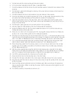
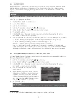
1. Press the ferrite core out of the retaining clip.
2. Disconnect all cables and tubes from the PCB controller (A9) in the following order:
– Ribbon cable temperature sensor (K7)
–
Cable humidifier connection (E6)
– Cable proportional valve (K6)
– Cable oxygen valve (K5) / Cable control valve (K9)
– Cable signal transmitter (K3)
– Cable oxygen sensor (K4)
– All tubes (While doing that, hold the pressure sensors tightly to avoid damaging their pins.)
– Ribbon cable operation panel (K1)
– Ribbon cable display (K2)
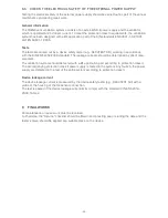
3. Pull off the O2 connection tube from the blower box and dispose of it.
4. Remove the 3 cable ties and dispose of them.


