Last updated: 08/13/20108 Rev. 9
17
Step 6:
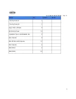
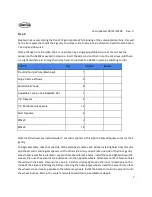
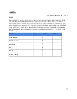
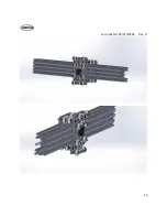
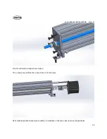
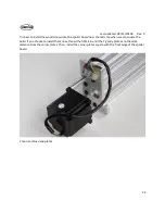
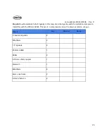
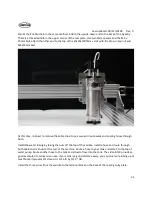
Step six we will build the X gantry. Note, on the X gantry there will be a piece of 1000mm length C-Beam
and a 1000mm length 20x20 V-Slot. The V-slot will be the exact same length as one piece of C-Beam.
The ends of the beam will be colored to indicate the matching C-Beam and 20x20 aluminum V-slot.
Please lay all out and find the piece of C-Beam that matches the 20 x20 x1000mm perfectly.
We will be mounting these two beams between the left and right Y gantry plates. We will also be
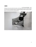
mounting the first stepper motor to drive the X axis. The motor can be mounted on the left or right Y
gantry plate. One should think about the final installation of the machine at this time and debate if there
will be an advantage to the motor being mounted on one side or the other for space reasons. The
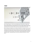
M5x15mm bolts will hold the beams to the Y gantry plates. The bearings will fit into the recesses in the
outside of the Y gantry plates. The ACME will thread through the anti-backlash nut on the X gantry we
built in a previous step.
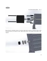
Prior to installation, it is advised to lightly sand down the ends of the ACME to allow the 608ZZ bearings
to slide over the ends of the ACME. Only about .2mm need be removed from the OD of the final 40mm
of both ends of the ACME. The bearings and ACME will be held in place by the 8mm lock collar on the
end opposite of the motor, and the coupling on the motor side.
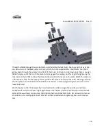
Install the X gantry on the C-Beam, thread the ACME through block on the X gantry, then install the two
side plates with the provided M5x15mm bolts.
Summary of Contents for R7
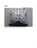
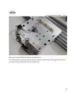
Page 6: ...Last updated 08 13 20108 Rev 9 6 Limit switch and barrier block shown installed ...
Page 19: ...Last updated 08 13 20108 Rev 9 19 ...
Page 27: ...Last updated 08 13 20108 Rev 9 27 ...
Page 28: ...Last updated 08 13 20108 Rev 9 28 ...
Page 30: ...Last updated 08 13 20108 Rev 9 30 ...

