80
9.4 Monitoring of communication data when alarms and warnings occur
The command data when an alarm or warning (e.g. data setting warning (A.94) or command warning (A.95))
occurs can be monitored through the following parameters. The following is the data when an alarm or
warning occurs under normal conditions.
CMD data in case of alarm or warning: Pn890
~
Pn8A6
RSP data in case of alarm or warning: Pn8A8
~
Pn8BE
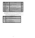
Command
byte order
Location where command data is saved in case of alarm or
warning
CMD
RSP
0
Pn890 = n.
XX
Pn8A8 = n.
XX
1
Pn890 = n.
XX
Pn8A8 = n.
XX
2
Pn890 = n.
XX
Pn8A8 = n.
XX
3
Pn890 = n. XX
Pn8A8 = n. XX
4
~
7
Pn892
Pn8AA
8
~
11
Pn894
Pn8AC
12
~
15
Pn896
Pn8AE
16
~
19
Pn898
Pn8B0
20
~
23
Pn89A
Pn8B2
24
~
27
Pn89C
Pn8B4
28
~
31
Pn89E
Pn8B6
32
~
35
Pn8A0
Pn8B8
36
~
39
Pn8A2
Pn8BA
40
~
43
Pn8A4
Pn8BC
44
~
47
Pn8A6
Pn8BE
(Note) 1. Data are arranged in small byte storage order and expressed in hexadecimal.
9.5 The fault causes and treatment measures can be judged from the actions and
states of servo motors.
The fault causes and treatment methods that can be judged from the actions and states of servo motors are as
follows.
Please cut off the power supply of the servo system when checking and handling the items in the thick wire
frame in the table below.
Fault contents
Reason
Confirmation method
The treatment measures
Don't
start
the
servo motor
The control power is not
switched on
Measure the voltage between
terminals of control power supply.
Connect the wires correctly to turn the
control power ON.
The main circuit power is not
connected
Measure the voltage between the
power input terminals of the main
circuit.
Connect the wires correctly to turn the
power supply ON of the main circuit.
The terminals of the input and
output signal connector (CN1)
have
wiring
errors
and
omissions
Confirm the connection status of
the input and output signal
connector (CN1) terminals.
Connect the input and output signal
connector (CN1) terminals correctly.
Wiring of servo motor main
loop cable and encoder cable
falls off
Confirm the connection status.
Correct wiring.
The servo motor is overloaded. Try no-load operation to confirm
the load status.
Lighten the load or replace it with a servo
motor with larger capacity.
The type of encoder used is
different from the setting of
Pn002 = n.
X
(encoder
use method)
Confirm the type of encoder used
and the setting of Pn002 =
n.X
.
According to the type of encoder used
Pn002 = n.
X
.
Incorrect distribution of input
signals
(Pn50A,
Pn50B,
Pn511, Pn516)
Confirm the distribution of input
signals (Pn50A, Pn50B, Pn511,
Pn516).
Input signals (Pn50A, Pn50B, Pn511,
Pn516) are correctly allocated.
No
servo
ON(SV-ON)
command
Confirm the command of the
upper device.
Input servo ON (SV_ON) command from
the upper device.
There is no ON(SENS_ON)
command
Confirm the command of the
upper device.
The commands are transmitted to the
servo drive according to the correct
sequence.
The forward rotation side drive
input
(P-OT)
signal
is
prohibited, and the reverse
rotation side drive input is
prohibited
(N-OT)
signal
remains OFF
Confirm the P-OT signal or the
N-OT signal.
Set the P-OT signal or N-OT signal to ON.
The forced stop input (FSTP)
signal remains OFF
Confirm FSTP signal.
• Set FSTP signal to ON.
• When the forced stop function is not
used, Please disable the function via
Pn516 = n.
X (forced stop of input
(FSTP) signal distribution).
Servo drive failure
-
Replace the servo drive.
The servo motor
runs
instantaneously
after
stop
motionless
Servo motor connection error Confirm wiring.
Correct wiring.
Incorrect wiring of encoder or
serial conversion unit
Confirm wiring.
Correct wiring.

