


C21UE102-2110
79
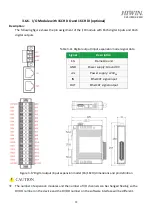
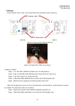
3.6.6.
I/O Module with 16CH DO and 16CH DI (optional)
Description:
The following figure shows the pin assignment of the I/O module with 16ch digital inputs and 16ch
digital outputs.
Table 3-11 Digital output/input expansion model signal data
Signal
Description
F.G
Frame Ground
GND
Power supply: Ground 0V
+Vs
Power supply: +24V
DC
IN
EtherCAT signal input
OUT
EtherCAT signal output
Figure 3-17 Digital output/input expansion model (16/16CH) dimensions and pin definition
The number of expansion modules and the number of I/O channels can be changed flexibly, so the
DI/DO number on the device and the DI/DO number on the software interface will be different.
Summary of Contents for RC4
Page 1: ...www hiwin tw User Manual Robot Controller RC4 Series Original Instruction ...
Page 64: ...C21UE102 2110 62 D SUB 44P INPUT NPN OUTPUT NPN ...
Page 65: ...C21UE102 2110 63 D SUB 44P INPUT PNP OUTPUT PNP ...
Page 77: ...C21UE102 2110 75 ...
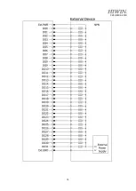
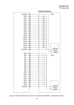
Page 79: ...C21UE102 2110 77 Figure 3 15 Digital output expansion model 32CH NPN configuration diagram ...
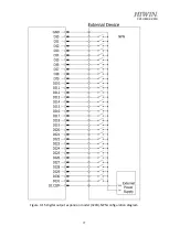
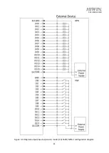
Page 80: ...C21UE102 2110 78 Figure 3 16 Digital output expansion model 32CH PNP configuration diagram ...


