


76
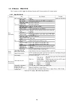
3.8.4 Connector Terminal Electrical Requirements
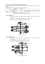
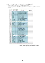
DIO I/F connector
IN/
OUT
Contents
Load current per OUT output
O
Allowable output: 80mA/point or less
Table 3.8-3 Connector terminal electrical requirements
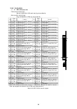
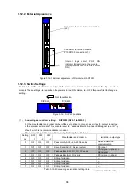
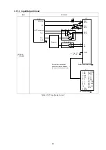
3.8.5 Output Circuit
(1) 12-24V is externally supplied to EXT-P. 5V cannot be used.
(2) When multiple output voltages are required, the voltage can be divided in units of 8 bits.
(3) Fuses are provided by units of 8 bits.
Figure 3.8-2 Output circuit
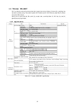
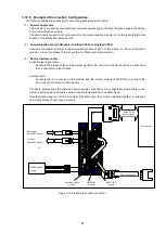
3.8.6 Fuses and LEDs
This module is provided with a fuse for every unit of 8 bits to prevent burnout by overcurrent.
When a fuse blows, the corresponding P0 to P3 LED (Green) located above and below the connector goes
OFF.
(When a fuse blows, turn OFF the power and check the circuit. Then, turn ON the power after a while)
Figure 3.8-3 Fuse and LED positions
EXT-Px
負荷
+24V
電源
OUT-01
トランジスタ
33K
Ω
OUT-32
トランジスタ
負荷
EXT-Gx
Fuse
33K
Ω
Fuse
HM-DO320C
50P
EXT-P0 LED
EXT-P1 LED
EXT-P2 LED
EXT-P3 LED
Fuse
Fuse
Fuse
Fuse
Fuse
Fuse
Fuse
Fuse
LEDs for EXT-P0 to P2
Fuses for
EXT-P0 to P3
LED for EXT-P3
+24V power supply
Transistor
Transistor
Load
Load
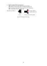
Summary of Contents for motionCAT HCPCI-MNT720M
Page 3: ......
Page 12: ...1 Warnings and Precautions...
Page 20: ...9 1 motionCAT Installation...
Page 109: ...98 4 Installation Guide...
Page 118: ...107 5 Device Driver Installation...
Page 122: ...111 6 Trial Operation...
Page 145: ...134 7 Accessories...
Page 147: ...136 8 Glossary...
Page 161: ...150 9 Connections to Drivers Supplied by Manufacturers...


