


62
(2)
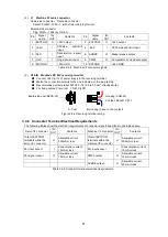
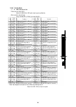
J1, J2 Connectors for pulse-motor signals (Motor1, 2)
Cable-side housing: 51353-1200, Contact: 56134-9000 (by Molex)
Module-side connector: 55959-1230 (by Molex)
Pin Signal name
IN/
OUT
Contents
1
TIM
I
Timing input
2
GND
I
GND
3
5V
O
5V output
4
CD_INH
O
Forced automatic current-down
prohibition
5
5V
O
5V output
6
C/S
O
Step angle switching output
(O.C.)
7
5V
O
5V output
8
MF-
O
Excitation OFF output (O.C.)
9
5V
O
5V output
10 CCW
O
CCW pulse output (O.C.)
11 5V
O
5V output
12 CW
O
CW pulse output (O.C.)
Table 3.5-4 J1, J2 connectors
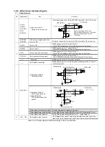
(3)
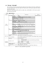
J3 Sensor connector (Sensor)
Cable-side housing: 51103-1200, Contact: 50351-8100 (by Molex)
Module-side connector: 53426-1210 (Molex)
Pin
Signal
name
IN/
OUT
Contents
1
24V
O
+24V output
2
+ELS1
I
(+) side end-limit input (Axis 1)
3
-ELS1
I
(-) side end-limit input (Axis 1)
4
DLS1
I
Deceleration sensor (Axis 1)
5
OLS1
I
Origin sensor (Axis 1)
6
GND
O
GND
7
24V
O
+24V output
8
+ELS2
I
(+) side end-limit input (Axis 2)
9
-ELS2
I
(-) side end-limit input (Axis 2)
10
DLS2
I
Deceleration sensor (Axis 2)
11
OLS2
I
Origin sensor (Axis 2)
12
GND
O
GND
Table 3.5-5 J3 connector
1
12
2
1
11
12
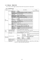
Summary of Contents for motionCAT HCPCI-MNT720M
Page 3: ......
Page 12: ...1 Warnings and Precautions...
Page 20: ...9 1 motionCAT Installation...
Page 109: ...98 4 Installation Guide...
Page 118: ...107 5 Device Driver Installation...
Page 122: ...111 6 Trial Operation...
Page 145: ...134 7 Accessories...
Page 147: ...136 8 Glossary...
Page 161: ...150 9 Connections to Drivers Supplied by Manufacturers...


