– 13 –
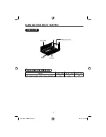
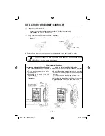
INSTALLATION OF WIRED REMOTE CONTROLLER
1. When connecting the wires via the wall’s
recessed slot;
Fix the bottom casing to the wall by
provided screw.
Assemble the top casing to the fixed
bottom casing.
(Refer to the illustration below for detail
installation)
Lead wires (4 strands)
are inserted through and
fastened via a rib-clip
Location of wall
mounting screw
Lead wires connector
Wires
Wires
Lead wires
connector
Wall recessed wiring installation (Supplied)
W
all mounting screws (2 pieces to
be used) (provided)
Inside top wiring installation (Alternative)
Wires
Wires
Lead wires
(4 strands)
Lead wires
connector
Wiring installation illustrations
2. When the wires to be connected from the inside top portion
of top casing;
Break off a perforated aperture located at the top portion
of the bottom casing by nipper. Smoothen the aperture
by cutter.
Fix the bottom casing to the wall by provided screw.
Connect the wires to the lead wires connector.
Mount the wires through the provided slot on top casing.
Assemble the top casing to the
fi
xed bottom casing
(Refer to the illustration below for detail installation)
Wall
mounting
screws
(2 pieces)
(provided)
(a) Connection to the electrical box;
●
Remove the cover of electric box
●
Connect the connector of wired remote controller to CN1102 of electrical board
●
Assemble back the cover of electrical box
(b) Wiring installation for wired remote controller (2 methods);
●
Wired remote controller casing can be opened by pressing the slots with minus screw driver (see below
diagram)
●
Decide the
fi
xing location of remote controller so that the length of wire shall be within 5 meters.
CAUTION
!
●
Do not cut the provided wire. Excess wire should be properly wound and
fi
tted at safe
place.
●
Do not join the wire with additional wire.
Top casing
Bottom casing
RAD-18-25-35-50NHA2 (EN2) 13
RAD-18-25-35-50NHA2 (EN2) 13
5/14/14 10:34 AM
5/14/14 10:34 AM


