


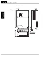


Step-by-Step Basic Installation
In
v
e
rt
er Moun
ting
and Install
a
tion
2–14
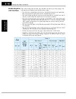
Determining Wire
and Fuse Sizes
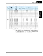
This section includes tables for 200V class and 400V class inverters (on the next page). The
following notes will help you read the tables in this section:
• Locate the row corresponding to the motor size and particular inverter in your application.
The maximum motor current determines the recommended wire sizes.
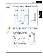
• The length column specifies that some inverters can optionally use a smaller wire gauge if
the wires are shorter than 10m and the inverter is located in an enclosure.
• Power Lines columns include wires connecting to terminals [R, S, T, U, V, W, P, PD, and N].
Only power input and motor leads will be fused: [R, S, T, U, V, and W]. The breaker ratings
(GFI—ground fault interrupter) are slightly higher than fuse ratings to allow for nominal
surges without tripping.
• The chassis ground columns list the Hitachi-recommended AWG and the minimal AWG for
UL conformity.
• The optional external braking resistor wiring only applies to a few models that have a built-
in braking unit. The other models use an optional external braking unit.
• Parallel wires increase effective wire gauge, and are denoted by “||” in the tables.
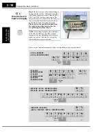
• Signal Lines, not listed in these tables, connect to the removable logic connector. The recom-
mended wire gauge for all wiring to the logic connector is 28 AWG (0.75 mm
2
). Be sure to
use shielded wire for any analog signals.
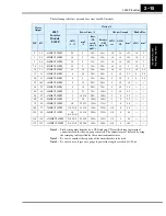
Motor
Output
200V
Inverter
Models,
L300P
Wiring *1
Power Lines *3
Chassis Ground
Brake Res.
HP
kW
AWG
*3
mm
2
*3
Fuse
(UL-
rated,
class J,
600V)
Breaker
( GFI
type) *2
AWG,
rec.
AWG,
UL
mm
2
AWG
mm
2
2
1.5
–015LFU2
14
2
10A
15A
16
14
1.25
14
2
3
2.2
–022LFU2
14
2
15A
20A
16
14
1.25
14
2
5
3.7
–037LFU2
10
3.5
20A
30A
10
12
3.5
10
3.5
7.5
5.5
–055LFU2
8
5.5
30A
50A
8
10
5.5
8
5.5
10
7.5
–075LFU2
6
8
40A
60A
8
10
8
8
5.5
15
11
–110LFU2
4
14
60A
75A
4
10
14
8
5.5
20
15
–150LFU2
2
22
70A
100A
3
8
22
8
5.5
25
18.5
–185LFU2
1
14 || 2
90A
100A
3
8
22
—
—
30
22
–220LFU2
1/0
38
100A
150A
2
8
30
—
—
40
30
–300LFU2
1/0
22 || 22
150A
200A
2
6
30
—
—
50
37
–370LFU2
1/0 || 1/0
30 || 30
175A
225A
1/0
6
50
—
—
60
45
–450LFU2
1/0 || 1/0
38 || 38
200A
225A
3/0
6
80
—
—
75
55
–550LFU2
2/0 || 2/0
60 || 60
250A
350A
3/0
4
80
—
—
100
75
–750LFU2
3/0 || 3/0
80 || 80
300A
350A
3/0
4
80
—
—


