


GR4000 Installation Guide Version 1.00 - Preliminary
520-10-014-20X
203
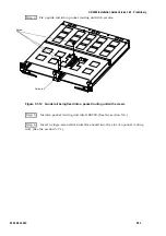
(2) Attachment of a DIMM
Step 1 Attach a memory module (DIMM) to the BCU by inserting it into its memory
slot as shown in the figure below. (The levers will be closed towards the direction (C) to
lock the memory module if you insert it into the slot deeply.)
Figure 5.8-2
Memory module being attached to the BCU
NOTE
Use a memory slot in ascending order of numbers starting with that
numbered 0 (Memory slot 0).
Step 2
Attach the basic control unit to the device.
(
As for the attachment of the
BCU, refer to the section 5.5 Additional Installation/Replacement of Basic Control
Units.
)
Basic control unit (BCU)
Memory module
(DIMM)
Lever
Lever
(
C
)
Memory slot 3
Memory slot 2
Memory slot 1
Memory slot 0
(
C
)