


Copyright © 2019, 2021, Hitachi, Ltd.
DKC910I
Hitachi Proprietary
[INST(RM)10-03-10]
Rev.2
INST(RM)10-03-10
10.3 Removing Controller Chassis
NOTICE:
• When it is assumed that the MP operating rate exceeds 70% if Controller Chassis
is removed, the removal of Controller Chassis is suppressed. Before removing
Controller Chassis, lower the MP operating rate.
• If a failure part exists in other than the Controller Chassis to be removed, or if a
drive for which drive copy or correction copy is in progress exists in the system, the
removal of Controller Chassis is suppressed. Check the system status before the
removal.
• The work time becomes longer depending on I/O load and write pending.
When the write pending rate of any of MPUs/CLPRs in the system exceeds 20%,
the removal of Controller Chassis is suppressed. Before removing the Controller
Chassis, lower the I/O load and write pending rate.
• When Virtual Partition Manager is used, the removal of Controller Chassis, which
causes the cache capacity of CLPR0 to be smaller than 4 GB, fails.
Before removing Controller Chassis, confirm that the cache capacity of CLPR0 is
greater than that of the Controller Chassis to be removed by at least 4 GB.
(Cache capacity of Controller Chassis to be r 4 GB
≦
Cache capacity of
CLPR0)
1. Connecting the Maintenance PC
Connect the Maintenance PC to the SSVP, and then log in to the SVP.
•
“
Attachment/Removal Procedure of Maintenance PC
”
•
“
Connection to the SVP
”
2. Starting the SVP window
From the menu of Web Console, click [Maintenance Components]-[Maintenance Other Components].
3. Changing the operation mode
Change the mode to [View Mode].
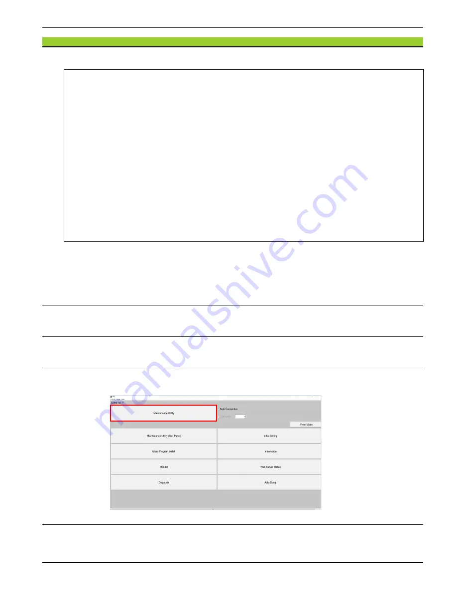
4. Starting the Maintenance Utility
In the SVP window, click [Maintenance Utility] (see
“
Starting Maintenance Utility
”
.).
5. Turning on the Locate LED
Turn on the Locate LED on the Controller Chassis to be removed (see
) to confirm the
location.


