


1417
12
Log
ical
par
titio
ni
ng man
age
r
Shared FC port status
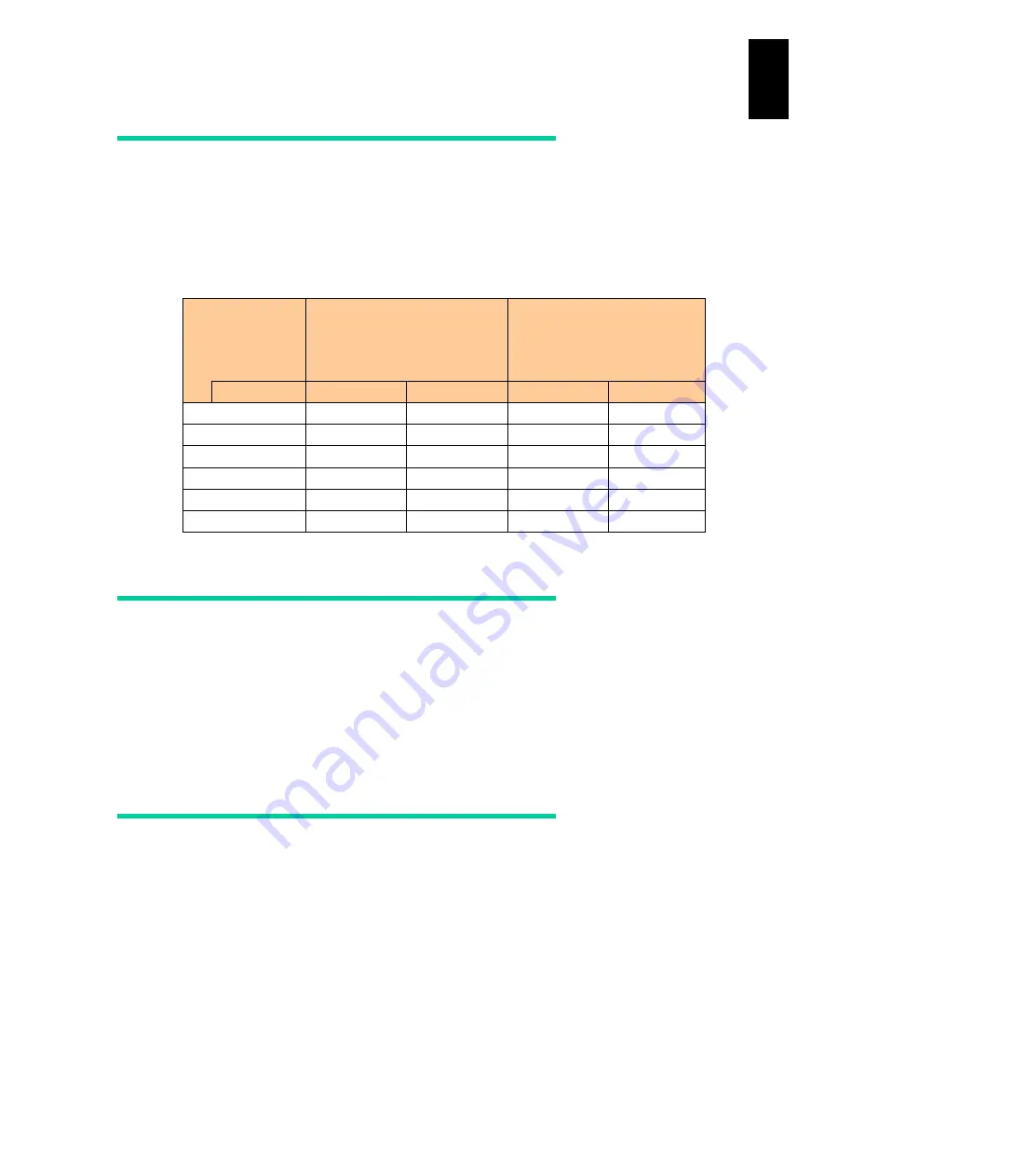
It is highly recommended that you should set the shared FC port status to Available. When
the shared port status is set to LinkDown, more time is required for booting LPAR
manager and changing the scheduling mode of the PCI device depending on the number
of LinkDown ports. The following table shows the relation between the number of installed
ports and required time for execution.
All FC ports
installed
Time required for LPAR
manager boot (seconds)
Time required for changing
scheduling mode of PCI
device and for executing
ForceRecovery
(seconds)
Port status
Available
LinkDown
Available
LinkDown
2
2’42”
4’4”
1’7”
1’48”
4
3’3”
4’22”
1’19”
3’45”
8
3’35”
6’23”
1’55”
5’33”
16
4’40’
10’3”
2’54”
9’21”
32
6’36”
16’51”
4’49”
16’29”
64
10’40”
31’55”
9’51”
30’47”
Notes on LPAR manager shutdown
There is no way to check when the LPAR manager configuration is saved. If the time is
unknown, you need to save the LPAR manager configuration before shutting down LPAR
manager. Press
F9
Save Configuration
on the LPAR manager Menu screen to save
LPAR manager configuration. If you shut down or reboot LPAR manager before saving
the configuration, newly changed values will be lost. See
for information about how to save LPAR manager configuration.
Flash memory failure
It is strongly recommended that you should regularly create backup files of LPAR
manager configuration in case of flash memory failure.
LPAR manager firmware 58-5X/78-5X or later versions automatically recover from flash
memory failure if it is not critical. A log “LPAR manager Loader detected the damage of
flash memory and load configuration files from SVP.” is collected in the LP system log at
automatic recovery. If this system log is collected every time you boot LPAR manager,
contact your reseller or consult maintenance personnel.
Summary of Contents for Compute Blade 2000
Page 1: ...MK 99BDS2K001 16 Hitachi Compute Blade 2000 User s Guide ...
Page 42: ...xlii Precautions for Safe Use Rear View of A1 A2 Chassis ...
Page 43: ...xliii Precautions for Safe Use Rear View of A2 Chassis ...
Page 44: ...xliv Precautions for Safe Use Server Blade ...
Page 45: ...xlv Precautions for Safe Use I O Slot Expansion Unit ...
Page 46: ...xlvi Precautions for Safe Use I O Module ...
Page 47: ...xlvii Precautions for Safe Use AC Power Input Module ...
Page 51: ...li How to Use the Manuals This page is intentionally left blank ...
Page 61: ...10 1 Before Use ...
Page 64: ...13 2 How to Use the System Equipment Rear view of A1 chassis Rear view of A2 chassis ...
Page 93: ...42 2 How to Use the System Equipment ...
Page 123: ...72 3 Connecting the System Equipment and Powering On ...
Page 272: ...221 5 Server Blade Setup 3 Check Del and click Go The following screen appears 4 Click Yes ...
Page 345: ...294 5 Server Blade Setup 12 Click Next The following screen appears ...
Page 351: ...300 5 Server Blade Setup 3 Check Delete and click Go The following screen appears 4 Click Yes ...
Page 426: ...375 5 Server Blade Setup 3 Check Delete and click Go The following screen appears 4 Click Yes ...
Page 430: ...379 5 Server Blade Setup 3 Click Go Hotspare is set to the specified hard disk ...
Page 479: ...428 5 Server Blade Setup ...
Page 717: ...666 6 Management Module Settings Details of a physical partition ...
Page 722: ...671 6 Management Module Settings Server blade details view ...
Page 723: ...672 6 Management Module Settings ...
Page 732: ...681 6 Management Module Settings Management module details view ...
Page 745: ...694 6 Management Module Settings Optional Physical WWN list view ...
Page 748: ...697 6 Management Module Settings Optional Physical WWN initialization view ...
Page 751: ...700 6 Management Module Settings ...
Page 754: ...703 6 Management Module Settings Power status details view ...
Page 767: ...716 6 Management Module Settings ...
Page 768: ...717 6 Management Module Settings ...
Page 769: ...718 6 Management Module Settings ...
Page 814: ...763 6 Management Module Settings Power status trend view partition ...
Page 817: ...766 6 Management Module Settings Access log display view ...
Page 819: ...768 6 Management Module Settings WWN change log display view ...
Page 879: ...828 7 Configuring the LAN Switch Module Link aggregation adding editing screen ...
Page 899: ...848 8 Configuring the 10 Gb DCB Switch Module ...
Page 919: ...868 10 Configuring the Fibre Channel Switch Module ...
Page 1535: ...1484 12 Logical partitioning manager ...
Page 1877: ...1826 14 14 When You Need Help ...
Page 1925: ...16 Glossary ...


