


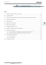


3 Servicing
Electrical components
SMGB0120 rev.0 - 11/2017
81
3
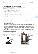
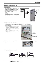
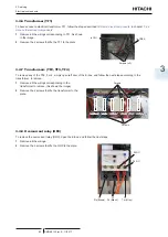
Clamp
lever
4
Push the clamp lever to fix the plate in horizontal
position at the top.
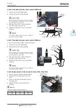
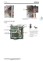
3.4.5
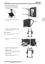
Removal of the PCB’s
PCBa
7- segment display
Pressure switches (PSW)
PSW3, PSW4 PSW5 PSW6
Pressure switches (PSW)
PSW1, PSW2
Switches (SW)
SW1, SW2
DSW1, DSW2, DSW3
DSW4, DSW5, DSW6
Dip switches (PSW)
Rotary switches
(RSW1)
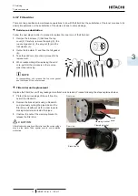
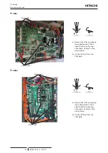
Plastic holder
Plastic holder
Plastic holder
a.
Remove the PCB by pressing
the expanded part of the 4
plastic holders, using long-
nose pliers, as shown in the
picture below.
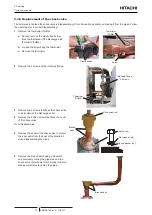
b.
Pull the PCB out from the
PCB plate.