


Repair - Pump Lower
3A6823A
15
Pump Repair
1.
Remove the packing nut (109) from the top of the
fluid cylinder (101). Do not remove either the lower
bracket (111) or locking ring (110).
2.
Remove the seal stack. Inspect seals and rings for
damage and wear, and replace as necessary
3.
Remove the inlet and outlet check housings (117
and 118; low- and medium-pressure pumps) or inlet
and outlet checks (122 and 123; high-pressure
pumps).
4.
Medium-pressure pumps only.
Remove the
o-rings (115), compression springs (116), and check
poppets (114).
5.
Low-pressure pumps only.
Remove the o-rings
(113 and 115), compression springs (116), and
check poppets (114). Inspect for damage and wear,
and replace as necessary.
NOTE:
Assuming the orientation shown in F
IG
. 3, and
with the point of lower bracket (111) pointing to the front
of the pump when installed, the inlet port will be to the
left and the outlet port to the right.
6.
Low- and medium-pressure pumps only.
Install
the small o-ring (115) onto the check poppet (114),
then install the poppet (115) and compression
spring (116) into the inlet check housing (117), as
shown.
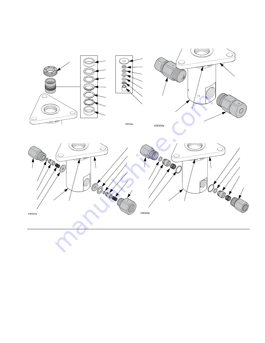
F
IG
. 3
Seal Stacks
High Pressure Checks
Low Pressure Checks
Low/Medium Pressure
High Pressure
102
107
106
105
104
103
102
108
107
106
105
104
103
102
109
122
123
111
110
117
115
114
116
113
113
115
114
116
118
110
111
101
101
Medium Pressure Checks
110
111
117
115
116
121
114
119
120
114
116
115
118
101