326
Transferring Data to the PC
16.4
Transferring Data to the PC
The supplied USB cable can be used to transfer data from the built-in drive or CF card to a PC.
For information on how to use the supplied application software for data analysis, refer to the application's
Help function.
To Install and startthe application software, refer to “16.5 Wave Viewer (Wv)” (page 327).
System requirements
PC running Windows Vista
®
, Windows 7, or Windows 8
CAUTION
To avoid equipment failure, do not disconnect the USB cable while communication is in
progress.
Use a common ground for the instrument and PC. Use of different ground circuits will
result in a potential difference between the instrument’s ground and the PC’s ground.
If the USB cable is connected while such a potential difference exists, it may result in
equipment malfunction or failure.
Instrument Settings
Procedure
Press the
SYSTEM
key to open the System screen, and then select the
[Interface]
sheet.
1
Move the cursor to
[Interface]
, and select
[LAN].
2
Move the cursor to
[USB Set]
, and select
[Mass storage
HDD]
and
[Mass storage CF].
Operations to the USB memory stick, built-in drive or CF card from the unit are restricted during
[Mass
Storage].
Furthermore, the printer prints at
[Slow/Fine]
, regardless of the
[Print Speed]
setting.
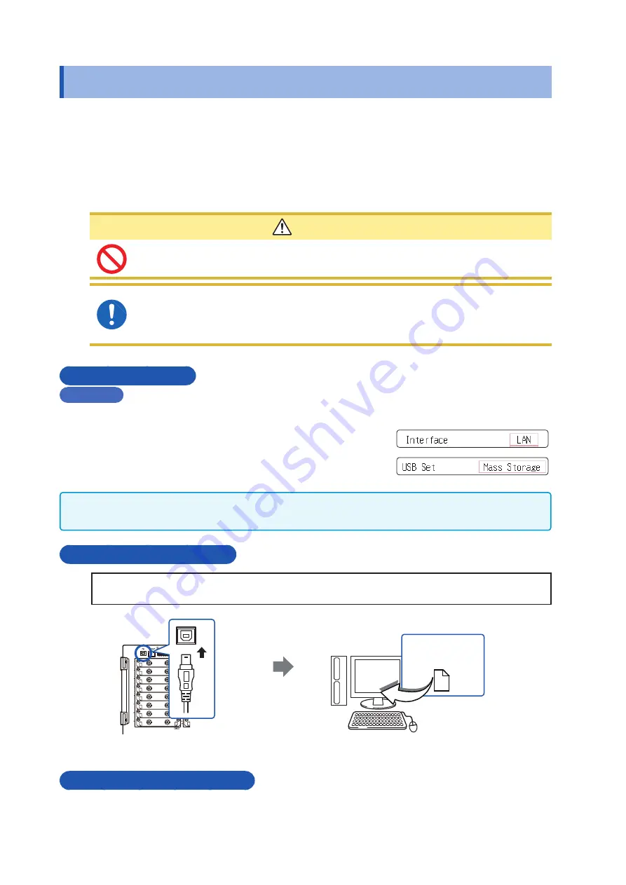
To Connect the USB Cable
Preparations
Stop measurement and make sure that the File screen is not displayed.
1
2
USB Connector
(Type B)
Insert the USB cable
into the USB port on the
instrument, being careful
to orient the connector
correctly.
Plug the other end of the
USB cable into a USB
interface on the PC.
Removable disk
Back side
When the connection is established, the PC will recognize the instrument as a removable disk.
The PC can now access data on the built-in drive or CF card of the instrument.
Disconnecting the USB Cable
To disconnect the USB cable of the instrument from a PC that is currently running, use the
[Safely
Remove Hardware]
icon and follow the prescribed steps.
Summary of Contents for MR8827
Page 19: ...14 Operation Precautions ...
Page 81: ...76 Start and Stop Measurement ...
Page 111: ...106 Manage Files ...
Page 125: ...120 Miscellaneous Printing Functions ...
Page 143: ...138 View Block Waveforms ...
Page 191: ...186 Setting Output Waveform Parameters ...
Page 291: ...286 FFT Analysis Modes Measurable Ranges With Octave Analysis 1 1 OCT 1 3 OCT ...
Page 292: ...287 FFT Analysis Modes 1 1 OCT 1 3 OCT 13 FFT Function ...
Page 293: ...288 FFT Analysis Modes 1 1 OCT 1 3 OCT ...
Page 295: ...290 FFT Analysis Modes ...
Page 309: ...304 Editor Command Details ...
Page 387: ...382 Module Specifications ...
Page 405: ...400 Dispose of the Instrument Lithium Battery Removal ...
Page 431: ...A26 FFT Definitions ...
Page 436: ......


