


13
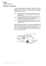
1.3 Identification of Controls and Indicators
1.3 Identification of Controls and Indicators
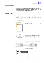
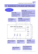
Front Side
LCD display
20 characters x 2 lines,
with backlight
Power LED
The LED indicates the power
ON status of the instrument.
The LED goes on in red when
power is turned on.
CAN LED
The LED goes on in green when the
CAN message assigned to the 8910's
output channel is input.
Online LED
This LED indicates whether the 8910 and PC
can communicate via the RS-232C.
The LED goes on in green when the ONLINE/
OFFLINE switch is set to the ONLINE side for
enabling communication.
The LED goes on in orange when the 8910 is
engaged in communication.
ESC (escape) key
Key used for various
settings.
SEL (select) key
Key used for various
settings.
ENT (enter) key
Key used for various
settings.
CAL (calibration) key
In calibration mode, a
calibration signal is output
only while this key is pressed.
CAL LED
The LED goes on in green
during calibration signal
output.
Summary of Contents for 8910
Page 1: ...8910 Instruction Manual CAN ADAPTER EN Aug 2018 Revised edition 7 8910A981 07 18 08H ...
Page 2: ......
Page 8: ...Contents vi ...
Page 18: ...Notes on Use 10 ...
Page 44: ...3 5 Operation Map 36 ...
Page 48: ...4 2 Program Setup 40 ...
Page 56: ...5 4 Operation Flowchart 48 ...
Page 78: ...6 6 Editing in Another Window 70 ...
Page 90: ...7 4 Setting the ID Filter 82 ...
Page 99: ...91 9 2 Setting Data Printout ...
Page 130: ...10 2 Using the 8910 with the 8841 8842 MEMORY HiCORDER 122 ...
Page 147: ......
Page 148: ......
Page 149: ......
Page 150: ......


