


System Manual Compact Systems
7 Start-Up
HI 800 141 E Rev. 2.02
Page 51 of 110
L- can only be earthed on one place within the system. L- is usually earthed directly behind the
power supply unit, e.g., on the busbar. The earthing should be easily accessible and well
separable. The earthing resistance must be ≤ 2
.
7.2.5.2
Earthing Connections
All HIMatrix devices have labeled screws for earthing. The wire cross-section for the connection
to the screw is 2.5 mm
2
. The earth wires must be as short as possible.
Provided that the DIN rail is earthed in accordance with the standard, mounting the HIMatrix
compact systems on the DIN rail already ensures a sufficient earth connection.
These measures ensure a reliable earth ground and compliance with the current EMC
requirements for HIMatrix systems.
7.2.5.3
Shielding
Sensor or actuator wires for analog inputs and outputs used in HIMatrix systems with shrouds
(F3 AIO, F35 and F60) must be laid as shielded cables. The shielding must be connected to the
HIMatrix system and the sensor or actuator housing and earthed on one end to the HIMatrix
system side to form a Faraday cage.
To earth the cable shielding, the F3 AIO 8/4 01, F35 and F60 have rails on the front that are
electrically connected to the housing potential. A clamp is used to connect the cable shielding to
the rail.
In all other devices, the shielding must be positioned in the controller housing, terminal box,
control cabinet, etc.
i
The shield clamp must not be used as a strain relief for the connected cable.
7.2.5.4
EMC Protection
Windows in the enclosure in which the HIMatrix system is installed are permitted.
Increased EMC interferences outside the standard limit values require appropriate measures.
i
For improved EMC, earth the housing.
The connection to the next grounding point must be as short as possible to achieve a low
earthing resistance.
7.2.6
Connecting the Supply Voltage
Protect the controller externally with a 10 A time-lag fuse.
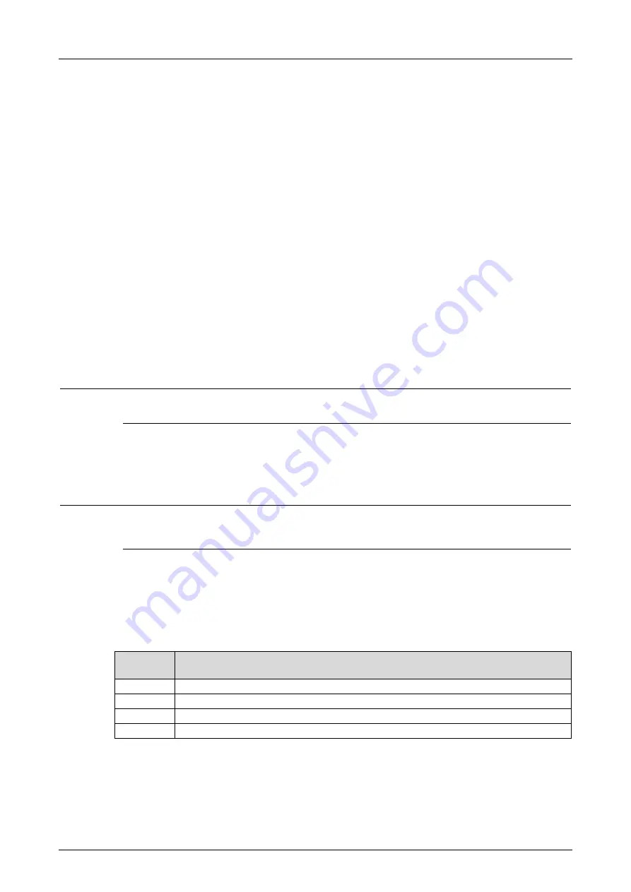
The operating voltage is connected using a detachable four-pole connector located on the
module's front plate. The connector can accept wires of up to a maximum of 2.5 mm².
Connec-
tion
Function
L+
Power supply L+ (24 VDC)
L+
Power supply L+ (24 VDC)
L-
Power supply L- (24 VDC ground)
L-
Power supply L- (24 VDC ground)
Table 27: Power Supply Connectors
The two clamp terminals L+/L+ and L-/L- of the device are internally bypassed and intended for
use in a two-wire supply. If the clamp terminals are connected to other devices, the maximum
current of 10 A must not be exceeded.
Check proper polarity, voltage and ripple prior to connecting the operating voltage 24 VDC.