background image

4

English

2328430

*2328430*

1.3 Product-dependent symbols

1.3.1 General symbols

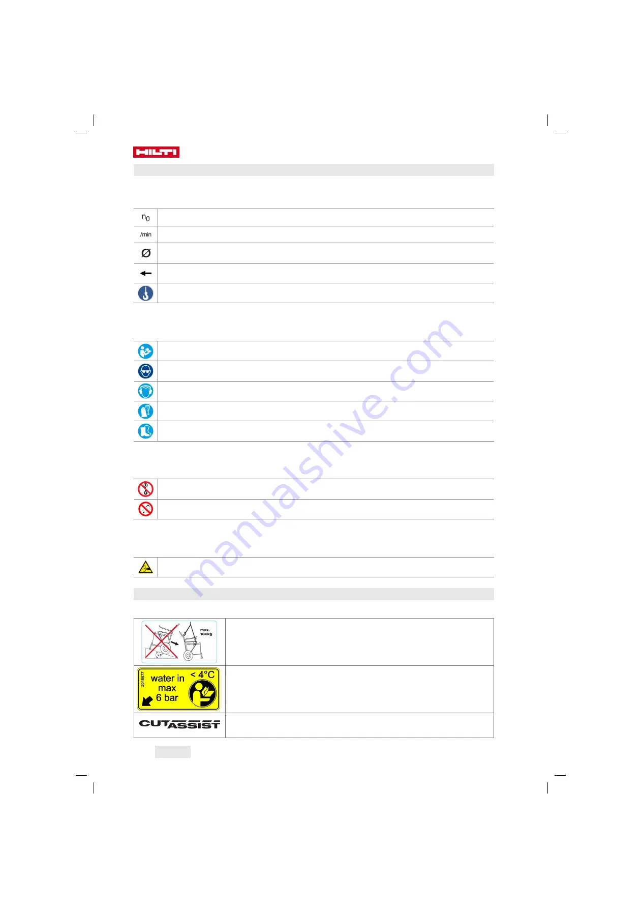
The following symbols are used on the product:

Rated speed under no load
Revolutions per minute
Diameter

Saw blade direction of rotation (arrow on the blade guard holder)

Suspension point provided for lifting by crane

1.3.2 Obligation symbols

The following obligation symbols are used on the product:

Read the operating instructions

Wear eye protection

Wear ear protection

Wear protective gloves

Wear safety shoes

1.3.3 Prohibition symbols

The following prohibition symbols are used on the product:

Lifting by crane prohibited

Use of high-pressure cleaning equipment prohibited

1.3.4 Hazard symbols

The following hazard symbols are used on the product:

Warning: risk of cutting injury

1.4 Stickers

Stickers on the product

On the transport trolley

Using the transport trolley

On the saw head

Maximum water pressure and action to be taken in the event of

risk of frost

On the saw head

The machine is equipped with the

Cut Assist

function.

Summary of Contents for DST 20-CA

Page 1: ...DST 20 CA English...

Page 2: ......

Page 3: ...DST 20 CA Original operating instructions...

Page 4: ......

Page 5: ...al power tool safety warnings 6 2 3 Additional safety instructions for wall saws 8 2 4 Safety measures at the danger areas 10 2 5 Safety during operation 11 2 6 Safety during transport 12 3 Descriptio...

Page 6: ...l cut 32 7 4 3 Installing inner flange flush cutting 33 7 4 4 Installing saw blade flush cut 34 7 5 Fitting the blade guard 36 8 Working with the saw 37 8 1 Checks before beginning sawing work 37 8 2...

Page 7: ...erious injury or fatality CAUTION CAUTION Draws attention to a potentially dangerous situation that could lead to personal injury or damage to the equipment or other property 1 2 2 Symbols in the oper...

Page 8: ...ons Wear eye protection Wear ear protection Wear protective gloves Wear safety shoes 1 3 3 Prohibition symbols The following prohibition symbols are used on the product Lifting by crane prohibited Use...

Page 9: ...dust Power tools create sparks which may ignite the dust or fumes Keep bystanders children and visitors away while operating a power tool Distractions can cause you to lose control Electrical safety G...

Page 10: ...source before making any adjustments changing accessories or storing the tool Such preventive safety measures reduce the risk of starting the tool accidentally Store idle tools out of reach of childr...

Page 11: ...ic shock Personal safety Stay alert watch what you are doing and use common sense when operating a power tool Do not use a power tool while you are tired or under the influence of drugs alcohol or med...

Page 12: ...ose intended could result in a hazardous situation Keep handles and grasping surfaces dry clean and free from oil and grease Slippery handles and grasping surfaces do not allow for safe handling and c...

Page 13: ...tains its stability while cutting work is in progress and also after removal of the part cut away In cooperation with the site engineer or architect check to ensure that no gas water electricity or ot...

Page 14: ...measures at the danger areas WARNING A risk is presented by moving parts by falling objects or debris that may fly off Falling or flying objects could cause serious injury Make sure that the area is...

Page 15: ...ts and to secure the parts of the object being cut As a basic rule never stand directly in line with the rotating saw blade Always use the appropriate correctly fitting blade guard type BG for normal...

Page 16: ...e saw system and its specified accessories Do not use the trolley to transport other items or materials Before transporting make sure that all removable items of equipment are securely fastened to the...

Page 17: ...head Remote control unit Transport trolley Blade guard center section Guide track Blade guard side section Accessories box Toolbox Saw blade Inner flange saw blade normal cutting Outer flange saw bla...

Page 18: ...cations given on the rating plate or in these operating instructions Overhead work is permissible only when additional safety measures are implemented No one is permitted underneath the saw when overh...

Page 19: ...65 saw blade guard Blade guard saw blades up to 650 mm 2051935 DST BG80 saw blade guard small Blade guard saw blades up to 600 mm 800 mm 238002 DS BG80 middle section Blade guard saw blades up to 600...

Page 20: ...Saw head Rated values guaranteed at an ambient temperature of max 18 C and at an altitude of max 2000 m above sea level Weight in accordance with EPTA Procedure 01 33 7 kg Rated speed 118 min 940 min...

Page 21: ...x 10 dB A when noise reducing silent saw blades are used DST 10 CA Sound power level LWA 114 5 dB A Sound pressure level LpA 96 9 dB A Sound level uncertainty KpA EN 15027 3 dB A 5 Planning 5 1 Cuttin...

Page 22: ...7 mm 83 mm 73 mm 60 mm 210 mm 148 mm 130 mm 106 mm 91 mm 80 mm 65 mm 220 mm 165 mm 143 mm 116 mm 99 mm 87 mm 70 mm 230 mm 185 mm 158 mm 127 mm 107 mm 94 mm 76 mm 240 mm 209 mm 175 mm 138 mm 117 mm 101...

Page 23: ...8 mm 480 mm 349 mm 490 mm 372 mm 500 mm 398 mm 510 mm 429 mm 520 mm 467 mm 530 mm 523 mm 5 3 Distance between rail supports a Max distance between 2 track supports 66 9 in 170 cm b Max track end proje...

Page 24: ...pports should be positioned as shown in the above illustration 5 5 Power source WARNING Risk of electric shock Severe injury and burns can result if any attempt is made to operate the tool without an...

Page 25: ...mm Extension cable con ductor cross section 2 58 kcmil 4 11 kcmil 6 53 kcmil 10 4 kcmil Extension cable length 40 m 40 70 m 70 110 m 110 180 m Extension cable length 130 ft 130 230 ft 230 360 ft 360...

Page 26: ...ave any questions about secure fastening The following instructions apply to use of the HKD D M12 flush anchor If you use a different type of anchor please follow the anchor manufacturer s instruction...

Page 27: ...rmal cutting 2 Engage the rail with the rail hooks in the rail supports and slide the clamping plates over the edge of the rail 3 Bring the rail supports into alignment at right angles to the rail and...

Page 28: ...upport Re install the screw after setting the track support to 45 3 Slacken the top clamping screw for the bevel cut angle 4 Fit the track onto the track supports 5 Slide the clamping plate over the e...

Page 29: ...33 mm 533 mm 5 239 mm 231 mm 256 mm 306 mm 356 mm 406 mm 505 mm 10 249 mm 202 mm 227 mm 276 mm 325 mm 374 mm 473 mm 15 262 mm 171 mm 195 mm 243 mm 292 mm 340 mm 437 mm 20 278 mm 138 mm 161 mm 208 mm 2...

Page 30: ...or cutting on stairs to the rail support 3 Slacken the clamping bolts for angle ad justment Clamping insert for cutting on stairs Rail End stop Securing screw for the rail support 4 Mount the rail on...

Page 31: ...s rail support to set the saw to a slight angle 6 7 Extending tracks Always use only the accessories intended for the purpose to extend the tracks Rail Tapered connector Eccentric pin 1 2 square pin w...

Page 32: ...the release button 2 and engage the clamping lever 1 in the bottom latched position opened If the locking lever cannot be latched on the opened or closed position do not proceed with the installation...

Page 33: ...hoses can result in damage to the equipment or other property Position the cables and hoses so that they can follow the movement of the saw head without being under tension Take care to ensure that t...

Page 34: ...n as described is highly dangerous Do not used parts that evince signs of damage or that are not in full working order If you find defects stop work immediately and replace the defective parts Before...

Page 35: ...e instructions Do not under any circumstances use an impact wrench or other similar power tools to tighten the tie rod You can leave the inner flange for normal cutting installed until you are going t...

Page 36: ...it slips into the mount of the saw arm arbor When the flange nut slips into the mount of the saw arm arbor the tie rod becomes easy to move and spring tension can pull it back to the initial position...

Page 37: ...cooling water slots are open in the holes correct cooling of the saw blade is not ensured 4 Grease the thread of the clamping screw with the grease provided for the purpose so that the clamping force...

Page 38: ...3 If applicable unscrew the 6 countersunk head screws from the inner flange 1 4 Set the inner flange flush cutting on the saw blade 2 5 Screw the 6 countersunk head screws into the face of the saw bl...

Page 39: ...arm arbor When the flange nut slips into the mount of the saw arm arbor the tie rod becomes easy to move and spring tension can pull it back to the initial position At least 6 full turns are necessar...

Page 40: ...dle section onto the blade guard holder 2 Fit the blade guard side section inserting the metal hook in the blade guard middle section 3 Secure the blade guard side section with the tensioning bar The...

Page 41: ...l cable are routed such that they will track the movement of the saw body smoothly and cannot come into contact with moving parts The track supports and tracks are positioned correctly and mounted sec...

Page 42: ...in line to the cooling water supply you must make sure that the water bypass is installed and open Without the water bypass the water pressure could damage the system The water bypass enables continuo...

Page 43: ...or on the blade guard 1 3 Install the suction channel at the back of the cut 2 and connect a dust extractor 3 9 Dismantling the saw system 9 1 Removing saw blade normal cutting 1 Remove the blade guar...

Page 44: ...r the tie rod has been slackened and removed 2 Fully unscrew the tie rod from the thread of the flange nut 3 Disengage the tie rod and use the tie rod to press the flange nut fully back into the inner...

Page 45: ...pump blow out the saw head until no further water is ejected To release the pump hose from the blow out adapter press down the release ring on the adapter and pull the hose out of the blow out adapte...

Page 46: ...mbrittlement After cleaning and maintenance make sure that all safety devices are refitted and check that these safety protective devices function correctly 10 1 Adjusting the guide rollers Clamping s...

Page 47: ...ation Clean if necessary Track Check the contact and running surfaces Clean if necessary Check the splines and the running surfaces for damage and wear replace the track if neces sary Check the tapere...

Page 48: ...e place if necessary Check the saw head for oil or water leakage and have it repaired if necessary Check the water flow and replace the mesh fil ter at the water supply connection if necessary Clean t...

Page 49: ...Repeat the flange installa tion procedure The play at the guide rollers exceeds the specified value Check the play at the rollers and adjust the rollers correctly If ad justment is not sufficient rep...

Page 50: ...se the clamping surfaces Threads of clamping screw and inner flange dirty or damaged Clean and check the threads of clamping screw and inner flange Thread of the clamping screw is stiff Grease the thr...

Page 51: ...owing it to enter the sewerage system 14 Manufacturer s warranty Please contact your local Hilti representative if you have questions about the warranty conditions 15 FCC statement applicable in US IC...

Page 52: ...Hilti registered trademark of Hilti Corp Schaan 20220523 2328430 2328430...

Reviews: