


CAUTION
: when getting down from the machine, do not place your foot on the scrubbing brush
head or side brush head brush.
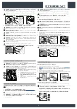
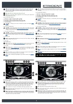
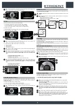
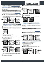
7. Grip the back of the seat (4) and turn the seat support plate to its maintenance position (
Fig.4
).
ATTENTION:
to prevent the seat from rotating, insert the retainer (5) into the slot (6) (
Fig.5
).
8. Disconnect the battery connector from the machine's main system connector (
Fig.6
).
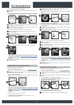
9. Grip the handle (7) and raise the recovery tank to the maintenance position (
Fig.7
).
ATTENTION
: to prevent the recovery tank from rotating, grip the handle (8) on the safety stop
lever (9) and position the lever in the second stop slot (
Fig.8
).
N.B.
: for battery maintenance and daily recharging, you must fully respect the indications
provided by the manufacturer or retailer.
CAUTION
: all installation and maintenance operations must be carried out by specialised
personnel.
NOTE
: before installing the battery, clean the battery compartment. Check that the connectors
on the cables supplied are functioning correctly.
ATTENTION:
check that the characteristics of the battery that you are looking to use are
appropriate for the type of work to be performed. Check the battery charge and the condition of
the contacts on the battery.
N.B.
: you are advised to only lift and move the batteries with lifting and transportation means
suitable for the specific weight and size
CAUTION
: the lifting hooks must not damage the blocks, connectors or cables.
10. Place the batteries or battery box in the dedicated compartment under the operator's seat.
4
5
6
4
6
5
7
8
7
9
8
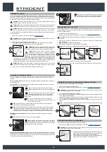
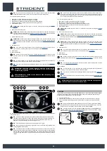
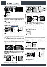
CONNECTING BATTERIES TO THE MACHINE
The batteries should be connected so as to obtain a total voltage of 36V.
ATTENTION
: it is recommended that all installation and maintenance operations be carried out
by expert personnel, trained at the specialised assistance centre.
CAUTION
: to prevent an accidental short circuit use insulated tools to connect the batteries, and
do not place or drop metal objects on the battery. Remove rings, watches and any clothing with
metal parts that may come into contact with the battery terminals.
The stages for connecting the batteries to the machine's
electrical system are as follows:
1. Using the supplied jumper cable (1), connect the
batteries to the "+" and "-" poles in sequence.
2. Connect the battery connector cable (2) to the
“+” and “-“ poles to obtain a voltage of 36V at the
terminals.
3. Connect the electric system connector (3) to the
battery connector (2).
3
2
1
RECHARGING THE BATTERIES
The batteries must be charged prior to first use, and whenever they no longer provide sufficient power.
N.B.
: Carefully read the Use and Maintenance Manual for the batteries you wish to use before
charging.
1. Bring the appliance to the zone where the batteries are charged.
2. Make sure the machine has been secured (see the section titled “
”).
ATTENTION
: park the appliance in an enclosed place, on a flat surface; near the appliance there
must be no objects that could either damage it, or be damaged through contact with it.
ATTENTION
: the room used to recharge the batteries must be adequately ventilated to prevent
the accumulation of gases that leak from batteries.
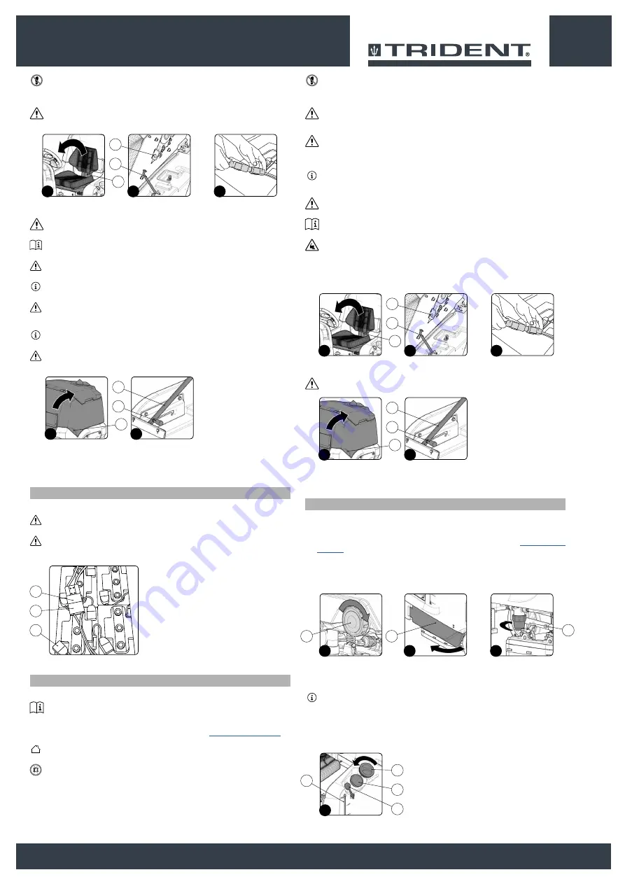
3.
Get off the machine.
CAUTION
: when getting down from the machine, do not place your foot on the scrubbing brush
head or side brush head brush.
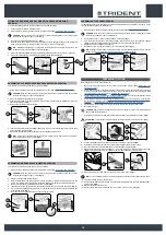
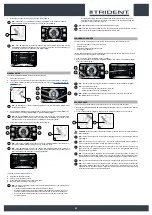
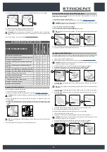
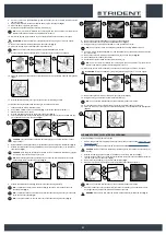
4. Grip the back of the seat (1) and turn the seat support plate to its maintenance position (
Fig.1
).
ATTENTION
: to prevent the seat from rotating, insert the retainer (2) into the slot (3) (
Fig.2
).
5. Disconnect the battery connector from the machine's main system connector (
Fig.3
).
ATTENTION
: the following operations must be carried out by qualified personnel. An incorrect
connection of the connector may cause a malfunction of the device.
6. Connect the external battery charger cable to the battery connector.
N.B.
: the coupling connector of the battery charger is consigned inside the bag containing this
instruction booklet, and must be assembled on the cables of the battery charger as indicated in
the instructions.
ATTENTION
: Before connecting the batteries to the battery charger, make sure it is suitable for
the batteries you want to use.
N.B.
: carefully read the use and maintenance instructions of the battery charger that is used for
charging.
CAUTION
: keep the recovery tank open for the duration of the battery recharging cycle to allow
gas fumes to escape.
7. Once the recharge cycle has been completed, disconnect the battery charger's cable from the
battery connector.
8. Connect the electrical system connector to the battery connector (
Fig. 3
).
9. Grip the back of the seat (1) and turn the seat support plate to the working position.
10. Grip the handle (4) and lower the recovery tank to the maintenance position (
Fig.4
).
ATTENTION
: to prevent the recovery tank from rotating, grip the handle (5) on the safety stop
lever (6) and position the lever in the stop slot (
Fig.5
).
1
2
3
1
3
2
4
5
4
6
5
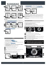
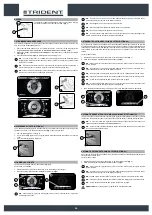
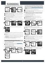
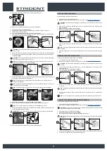
FILLING THE SOLUTION TANK
Before filling the solution tank, carry out the following steps:
1.
Take the machine to the usual place for filling the solution tank.
2. Perform the procedure for securing the machine ( see the section titled “
3. Check to make sure that the solution tank drainage cap (1) is closed. If this is not the case, close
it (
Fig.1
).
4. Move to the left side of the machine and open the left side casing (2) (
Fig.2
).
5.
Check to make sure that the water system's filter cap (3), located on the rear left side of the
machine, is closed, and close it if necessary (
Fig.3
).
The solution tank can be filled with water in two different ways:
•
Removing the cap (4) and filling the solution tank by means of a rubber hose or a bucket (
Fig.4
).
N.B.
: Check that the filter (5) under the filler cap (4) is positioned correctly; this is to prevent
impurities and dirt causing the appliance's water system to malfunction (
Fig.4)
.
•
Using the filler hose (6) (
Fig.4
). This supports the water hose on its own, but be sure to remove the
cap (4) to allow adequate air venting.
6. Fill with clean water, at a temperature not higher than 122 °F and not lower than 50 °F. The amount
inside the tank can be seen by means of the level tube (7) on the front left of the seat (
Fig.4
).
2
3
1
1
2
3
4
7
5
6
4
17