background image


51 

Chapter 5 Hardware Maintenance and Replacement


Hillstone


Hillstone SG-6000 X-Series Hardware Reference Guide


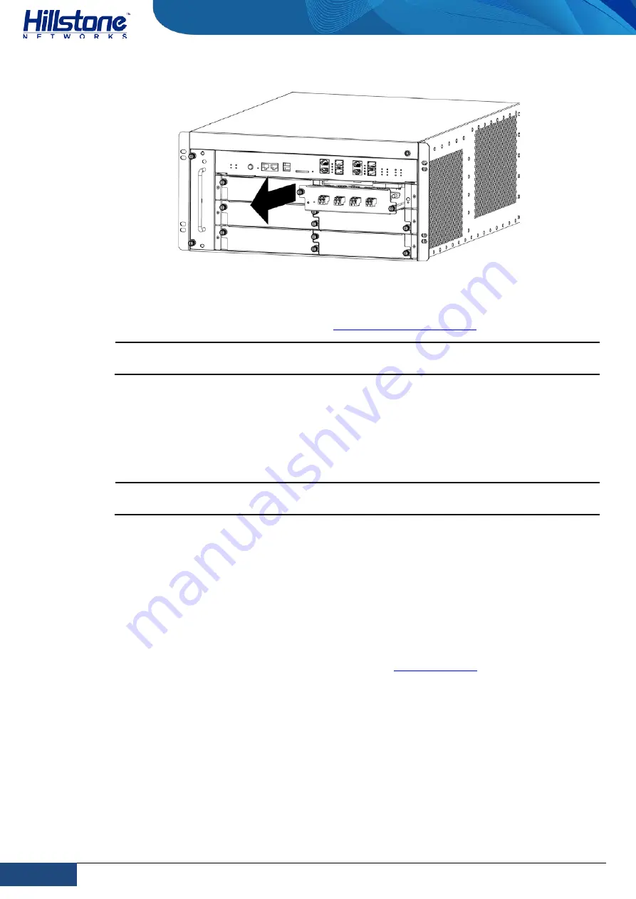
Figure 5-5: Replacing a Bypass Module 


5.


Put the removed module into an antistatic bag or on a flat antistatic table. 

6.


Install a replacement module (see 

Installing a Bypass Module

). 

Note: If you do not want to install a new module, apply a blank plate over the slot to 

avoid dust falling into the chassis. 


Replacing the Cooling System Components 

The cooling system of the device consists of 2 fan trays each of which has 6 fans and 
1 air filter. When the ventilation is inadequate due to fan failure or air filter block, you 
need to change the fan tray or the air filer.  

Note: You should change your fan trays at least once a year even they can work 

normally. 


Replacing a Fan Tray 

The chassis has a fan tray installed vertically on each of its sides. To prevent over-
heating, you should install a replacement fan tray immediately after you remove the 
existing one. The fan tray is hot-swappable. 

To replace a fan tray, take the following steps: 

1.


Wear an electrostatic discharge (ESD) strap around your bare wrist and connect 
the strap to an ESD point on the chassis. See 

ESD Prevention

. 

2.


Use a Phillips screwdriver to loosen the screws on the fan tray. 

3.


Hold the handle of the fan tray and pull it out a little to disconnect it to power. 
Wait till the fans stop spinning. 

Summary of Contents for SG-6000-X7180

Page 1: ...Hillstone StoneOS User Manual Hillstone SG 6000 X Series Hardware Reference Guide www hillstonenet com TW HW XS EN V1 0 Y16M05...

Page 2: ...hazardous substance in the material is below the limit requirement defined in Requirements for Concentration Limits for Certain Hazardous Substances in Electronic Information Products SJ T11363 2006 i...

Page 3: ...allation Preparation Chapter 3 Installation Chapter 4 Boot and Configuration Chapter 5 Hardware Maintenance and Replacement Chapter 6 Troubleshooting Document Conventions This manual uses the followin...

Page 4: ...14 XFP Port 15 QSFP Port 16 SFP Port 17 SD Card Slot 18 CLR Button 19 Cooling System 19 Chapter 2 Installation Preparation 21 Overview 21 Site Preparation 21 Temperature Humidity Specifications 21 Cle...

Page 5: ...r Module 35 Installing a DC Power Module 36 Connecting Cables 37 Tools Required 37 Grounding the Chassis 37 Connecting the Console Cable 38 Connecting the Ethernet Optical Cable 39 Connecting an AC Po...

Page 6: ...System Components 51 Replacing a Fan Tray 51 Replacing an Air Filter 52 Chapter 6 Troubleshooting 54 Overview 54 Losing the Administrator Password 54 Troubleshooting the Expansion Module 54 Troublesho...

Page 7: ...e Front Panel 27 Figure 3 2 ESD Point on the Front Panel 27 Figure 3 3 Installing Rack mounting Ears 29 Figure 3 4 Installing the Device in a Rack 29 Figure 3 5 Installing an SCM 31 Figure 3 6 Install...

Page 8: ...Console Port Attributes 14 Table 1 6 Auxiliary Port Attributes 14 Table 1 7 USB Port Attributes 14 Table 1 8 SFP Port Attributes 15 Table 1 9 SFP Optical Module Attributes 15 Table 1 10 XFP Port Attr...

Page 9: ...ons Designed for ISP data center and large enterprise SG 6000 X7180 has a strong processing ability of 360 Gbps integrate high performance reliability and capacity reduce network complexity centralize...

Page 10: ...ne Console port one Auxiliary port one CLR button six general expansion slots one fan tray and several LED indicators Figure 1 3 SG 6000 X7180 Front Panel Table 1 1 SG 6000 X7180 Front Panel Descripti...

Page 11: ...s 20 Slot1 Slot6 General expansion slots 7 CON Console port 14 Slot1 Slot6 Slot status LED Back Panel SG 6000 X7180 back panel consists of four power supply slots four general expansion slots two SCM...

Page 12: ...le Hillstone Hillstone SG 6000 X Series Hardware Reference Guide No Label Description No Label Description No Label Description expansion slots LED Indicators The following table describes the LED ind...

Page 13: ...devices are in an HA cluster This device is working as the salve Red Blinking HA function has failed Off High Availability is disabled SD Green Always on SD card has been inserted and is in normal sta...

Page 14: ...module is standby Red Always on The fan of power module or voltage output has failed Red Blinking The power module is using overcurrent protection Off No power input LED on the fan tray Green Always o...

Page 15: ...e SG 6000 X7180 hardware modules include System Control Module Security Service Module QoS Service Module I O Module and bypass module A normal functioning device requires at least one SCM one SSM one...

Page 16: ...y Service Module SSM is a hardware platform card which performs data processing other than QoS You must install at least one SSM in the device and can install more to escalate system performance SSMs...

Page 17: ...100 QSM QoS Service Module QSM is a hardware platform card which solely performs Quality of Service QoS processing Without QSM the device cannot process QoS You can install one or more QSMs in general...

Page 18: ...QSM modules You must install at least one IOM and can install more to increase port amount IOM should be installed in general expansion slots Slot1 Slot10 but the IOM 2Q8SFP and IOM 8SFP module canno...

Page 19: ...11 Chapter 1 Product Profile Hillstone Hillstone SG 6000 X Series Hardware Reference Guide Figure 1 11 IOM 4XFP 100 Figure 1 12 IOM 2Q8SFP 200 Figure 1 13 IOM 2Q8SFP...

Page 20: ...er failure or system reboot the two networks are connected directly by the bypass module therefore the device is bypassed You can install bypass module s in general expansion slots Slot1 Slot10 For mo...

Page 21: ...connect the other two to a different power source This can ensure that when a power source fails the other power modules powered by the different source can begin to work immediately If you want to in...

Page 22: ...n the PC to configure the appliance Transmission Medium Console Cable Auxiliary Port Hillstone SG 6000 X7180 provides an RS 232C asynchronous serial auxiliary port Table 1 6 Auxiliary Port Attributes...

Page 23: ...mended If SFP optical module is applied to SFP port you should use cable with LC type optical connector Hillstone SG 6000 X7180 supports five types of 1000Base FX SFP optical modules All modules are h...

Page 24: ...1550nm Ultra long Haul Single mode Optical Module 1550nm Connector LC Fiber Type 50 125 m multimode fiber 62 5 125 m multi mode fiber 9 125 m single mode fiber 9 125 m single mode fiber 9 125 m single...

Page 25: ...de fiber Maximum Transmission Distance 0 3km 984 3ft 0 033km 108 3ft 10km 40km 80km Central Wavelength 850nm 850 1310nm 1550nm 1550nm Caution To avoid dust falling into the QSFP socket you should plac...

Page 26: ...FP port SD Card Slot Hillstone SG 6000 X7180 has an SD card slot for SD storage card on the front panel SD card stores the data of the Network Behavior Control log messages The highest capacity for SD...

Page 27: ...ng the appliance clears all existing configurations To restore the factory default settings take the following steps 1 Turn off the power of the appliance 2 Press the CLR button in the pinhole and swi...

Page 28: ...rdware Reference Guide From the front of the chassis there is air intake on the left side of the device Air is pushed from the left intake and then goes through the chassis cage The air is exhausted o...

Page 29: ...or place You should follow the instructions in this section to ensure that your site is properly prepared for the device installation Temperature Humidity Specifications Table 2 1 specifies the enviro...

Page 30: ...in the way of capacitance coupling inductance coupling electromagnetic radiation and common impedance including the grounding system coupling To prevent or reduce EMI Take measures to protect the powe...

Page 31: ...0mm deep and 225mm high The rack should be strong enough to support the weight of a fully configured device which is approximately 53 0kg Rack Clearance Requirements When planning the installation sit...

Page 32: ...0kg Note The device is maximally protected inside the shipping carton Do not unpack it until you are ready to begin installation To unpack the package take the following steps 1 Move the shipping cart...

Page 33: ...can be used for repacking or transportation Verifying the Parts Received When you receive the product a packing list is included inside the accessory box Verify the parts and items you received agains...

Page 34: ...Off the FirewallDevice 8 Verify the installation according to Verification after Installation Safety Requirements To avoid personnel injury or harm to the device follow the guidelines in this section...

Page 35: ...electrostatic discharges ESD follow the rules Always use ESD wrist strap which should be directly contact with your skin Caution For safety periodically check the resistance value of the ESD strap Th...

Page 36: ...o move and install the device If you use a lift to install the device see Installing the Device Firewall Using a Lift if you do not use a lift see Installing the Firewall Device without a Lift Tools R...

Page 37: ...ight side panels of the chassis respectively Figure 3 3 Installing Rack mounting Ears 4 Load the chassis steadily on the center of the lift platform 5 Use the lift to move the chassis to the rack or t...

Page 38: ...ower modules all expansion modules SSM SCM QSM and IOM blank plates and fan trays 4 Label all the removed parts so that you can reinstall them in the correct location 5 Move the chassis in front of th...

Page 39: ...rge ESD strap around your bare wrist and connect the strap to an ESD point on the chassis See ESD Prevention 2 Take SCM out from its antistatic bag 3 Identify the slot of SCM 4 If the slot is covered...

Page 40: ...side faces you and slide the SSM into the slot until you feel resistant as shown in Figure 3 5 Figure 3 6 Installing an SSM SSM 20 6 Tighten the screws on the SSM with a Phillips screwdriver 7 To ins...

Page 41: ...SFP and IOM 8SFP module cannot be installed in the Slot7 expansion slot The following section takes IOM 16SFP as an example to describe the installation of IOM To install an IOM take the following ste...

Page 42: ...The bypass module is installed in Slot1 to Slot10 To install a bypass module take the following steps 1 Wear an electrostatic discharge ESD strap around your bare wrist and connect the strap to an ES...

Page 43: ...n there are four power modules installed in the device two of them are working normally to supply power and the other two are for redundancy If you want to install the SSM 200 QSM 200 or IOM 2Q8SFP 20...

Page 44: ...the chassis panel Figure 3 10 Installing an AC Power Module Installing a DC Power Module To install a DC power module take the following steps 1 Make sure the power module is not connected to any powe...

Page 45: ...r cable Ethernet cable optical cable and power cable Tools Required The following tools are required Phillips screwdriver ESD wrist strap Grounding the Chassis To avoid electrostatic discharge you mus...

Page 46: ...llips screwdriver 7 Arrange the grounding cable so that it does not block the hardware components and it does not drape where people might trip over Connecting the Console Cable The device provides an...

Page 47: ...ible with single mode or multi mode cable All SFP and XFP optical modules use LC type optical connector therefore you should connect the optical modules using optical fiber ended with LC type connecto...

Page 48: ...into the XFP port before connecting the LC type connector to the module Keep the followings in mind when connecting fiber cables The curvature radius should be greater than 10cm Avoid excessive bendin...

Page 49: ...external DC power source Hillstone does not provide DC power cables Warning Before performing the procedure ensure that the cable is not connected with any power source and make sure the cables will n...

Page 50: ...utton on the front panel for four seconds to shut down the device immediately Note The device requires at least two fan trays and one SCM to work normally Verification after Installation Verify the fo...

Page 51: ...Telnet or SSH Console CON Connection For initial system configuration you have to establish a Console connection environment connect the device to a console terminal through its Console port To connec...

Page 52: ...nning status Enter a question mark to get help on commands whenever you want WebUI The ethernet0 0 e0 0 port has a default IP address of 192 168 1 1 24 and all the management functions of this port ar...

Page 53: ...etwork requires different topology design working mode and policy configuration The basic configurations may include 1 Create security zones including the link layer L2 and network layer L3 Bind diffe...

Page 54: ...ing system or replace a fan tray See Replacing the Cooling System Components When you maintain the hardware components note that Always wear ESD strap on around your bare wrist See ESD Prevention When...

Page 55: ...Wear an electrostatic discharge ESD strap around your bare wrist and connect the strap to an ESD point on the chassis See ESD Prevention 3 Loose the screws of the DC power cable using a Phillips screw...

Page 56: ...plate over the slot to avoid dust falling into the chassis Replacing an SSM The following section takes SSM 20 as an example to describe how to replace an SSM To replace an SSM take the following ste...

Page 57: ...he strap to an ESD point on the chassis See ESD Prevention 2 Use a Phillips screwdriver to loosen SCM screws until they pop out 3 Hold the screws and pull the QSM straight out of the chassis as shown...

Page 58: ...t antistatic table 6 Install a replacement module see Installing an IOM Note If you do not want to install a new module apply a blank plate over the slot to avoid dust falling into the chassis Replaci...

Page 59: ...ate due to fan failure or air filter block you need to change the fan tray or the air filer Note You should change your fan trays at least once a year even they can work normally Replacing a Fan Tray...

Page 60: ...ting it will automatically switch off the power supply Replacing an Air Filter The air filter is inside the fan tray To avoid system overheating install the fan tray with a replacement air filter imme...

Page 61: ...eshes and the air filter 10 Place the air filter set over the fan tray and tighten all the screws removed in Step 3 11 Grasp the fan tray with the front panel screws on the right side of your palm Sli...

Page 62: ...iew the status of all modules on the command line interface Troubleshooting the Cooling System The cooling system consists of two fan trays and an air filter A malfunctioning fan tray or dust full air...

Page 63: ...on System The Console configuration terminal shows system booting message when the appliance is powered on If the configuration system has failed it displays error information or nothing at all If the...

Page 64: ...illstone PnPVPN UTM Plus are trademarks of Hillstone Networks All other trademarks or registered marks are the property of their respective owners Hillstone Networks assumes no responsibility for any...

Reviews: