background image

Control Terminal’s User Manual 

13 


3.3


Interface Description 

1

2

3

5

6

4

7

8

9

10

11

12

13

15

16

14


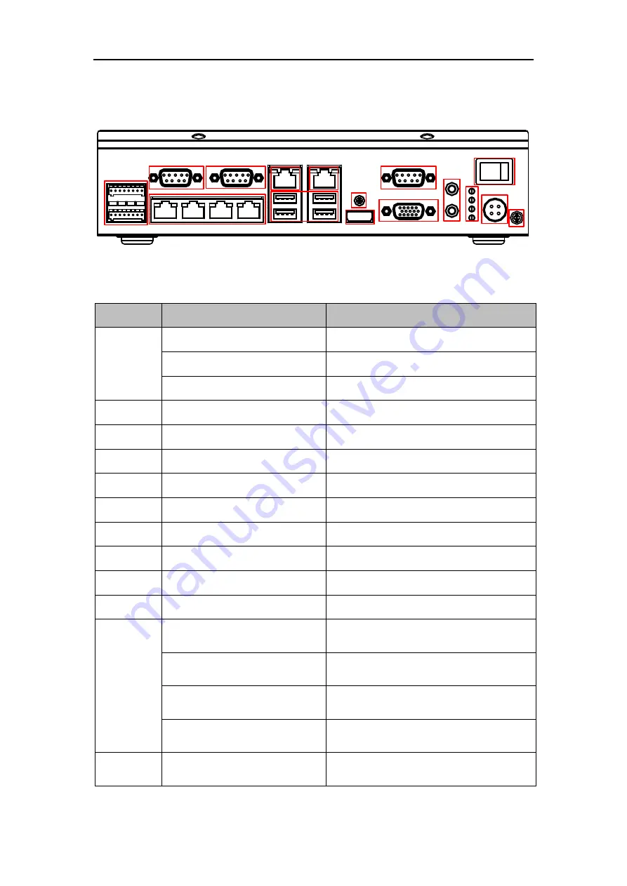
Figure 3-3


Interface Introduction 

Figure 3-4


Interface Description 

No. 

Name 

Description 

ALARM OUT 

4-ch alarm outputs 

ALARM IN 

2-ch alarm inputs 

RS-485 

2 RS-485 interfaces 

2/3/10 

RS-232 

3 RS-232 interfaces 

LAN1 

4 10/100M Ethernet Interfaces 

G1 

10/100/1000M Ethernet Interface 

G2 

100/1000M Ethernet Interface 

USB 

USB Interface 

Screw 

Lock Screw 

HDMI 

HDMI 

11 

VGA 

VGA Interface 

12 

AUDIO IN/OUT 

1-ch audio input/output 

13 

Power Indicator 

Indicator goes to green if power is 

connected. 

Alarm Indicator   

Indicator goes to red if the alarm is 

triggered. 

HDD Indicator 


The green indicator flashes when 

HDD is working. 

Working Status Indicator


The indicator stays in green when the 

device is working normally. 

14 

POWER 

Power switch, press 5 seconds to turn 

on/off the device.   

Summary of Contents for DS-TPE100

Page 1: ...Control Terminal s User Manual User Manual UD 6L0201D1989A01 Control Terminal TPE100...

Page 2: ...al includes instructions for using and managing the product Pictures charts images and all other information hereinafter are for description and explanation only The information contained in the Manua...

Page 3: ...IRUS INSPECTION OR OTHER INTERNET SECURITY RISKS HOWEVER HIKVISION WILL PROVIDE TIMELY TECHNICAL SUPPORT IF REQUIRED SURVEILLANCE LAWS VARY BY JURISDICTION PLEASE CHECK ALL RELEVANT LAWS IN YOUR JURIS...

Page 4: ...der the EMC Directive 2004 108 EC the RoHS Directive 2011 65 EU 2012 19 EU WEEE directive Products marked with this symbol cannot be disposed of as unsorted municipal waste in the European Union For p...

Page 5: ...drop the device or subject it to physical shock Proper configuration of all passwords and other security settings is the responsibility of the installer and or end user In the use of the product you m...

Page 6: ...ow the tips below to lower the damage might be caused by ESD o Wear a wrist strap and touch the metal parts of the device with the wrist strap o Touch the metal part on the machine instead of the comp...

Page 7: ...s User Manual 6 unit Use the device in conjunction with an UPS if possible Power down the unit before connecting and disconnecting accessories and peripherals A factory recommended HDD should be used...

Page 8: ...anual 8 Chapter 2 Introduction 9 2 1 Product Overview 9 2 2 Performance 9 2 3 Specification 10 2 4 Shipping Storage Requirement 11 Chapter 3 Installation 12 3 1 Appearance 12 3 2 Dimension 12 3 3 Inte...

Page 9: ...l Chapter 1 About This Manual Purpose This document introduces the DS TPE100 Control Terminal and relevant settings of the product Intended Audience This document is intended for Technical support eng...

Page 10: ...cture with good heat dissipation The control terminal is applicable to the challenging environment of dusty and high electromagnetic interference Figure 2 1 Overview of Control Terminal 2 2 Performanc...

Page 11: ...aces 2 RS485 interfaces 3 RS232 interfaces 1 VGA interface 1 HDMI interface 1 audio interface LINE in Line out 1 12V DC power input Others 3 5 HDD 1 pcs Adapter 60w Consumption 40W at max 2 3 Specific...

Page 12: ...ended that the device is packed in its original packing when shipping Make sure the device is away from the flammable combustible and corrosive objects and the rain snow and liquid as well Storing It...

Page 13: ...Control Terminal s User Manual Chapter 3 Installation 3 1 Appearance The device appearance is shown below Figure 3 1 Appearance 3 2 Dimension 245 170 65 u 0 3 Figure 3 2 Dimension...

Page 14: ...rfaces 5 G1 10 100 1000M Ethernet Interface 6 G2 100 1000M Ethernet Interface 7 USB USB Interface 8 Screw Lock Screw 9 HDMI HDMI 11 VGA VGA Interface 12 AUDIO IN OUT 1 ch audio input output 13 Power I...

Page 15: ...ad Thermal Pad HDD Radiator Figure 3 5 Assemble the HDD Assemble the HDD first before you install the HDD to the device Steps 1 Align the copper foil to one side of the HDD and fix the thermal pad to...

Page 16: ...al module with the standoffs and secure the thermal module with by tightening the lock screws 3 Install the HDD to the standoffs and tighten the lock screws 4 Connect the HDD cables to the correspondi...

Page 17: ......

Reviews: