background image

Network Video Recorder User Manual 

90 

Chapter 6 Smart Analysis 

Note 

The available functions in this chapter may vary according to different models. 


6.1 Engine Configuration 

Each engine processes a specified VCA type as its working mode. You can configure the engine 
working mode as your desire. 

Steps   
1. Go to Smart Analysis → Engine Settings → Engine Configuration


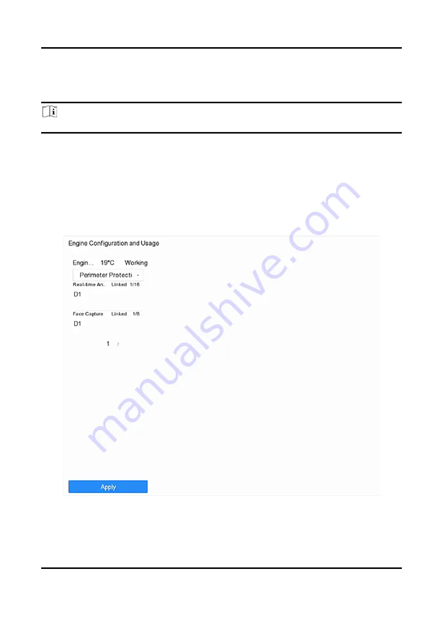
Figure 6-1 Engine Configuration 

2. Configure each engine usage. You can view the engine temperature and linked channel status of 

each function. 

Summary of Contents for DS-7600NXI-8P/S Series

Page 1: ...Network Video Recorder User Manual ...

Page 2: ...DED AS IS AND WITH ALL FAULTS AND ERRORS HIKVISION MAKES NO WARRANTIES EXPRESS OR IMPLIED INCLUDING WITHOUT LIMITATION MERCHANTABILITY SATISFACTORY QUALITY OR FITNESS FOR A PARTICULAR PURPOSE THE USE OF THE PRODUCT BY YOU IS AT YOUR OWN RISK IN NO EVENT WILL HIKVISION BE LIABLE TO YOU FOR ANY SPECIAL CONSEQUENTIAL INCIDENTAL OR INDIRECT DAMAGES INCLUDING AMONG OTHERS DAMAGES FOR LOSS OF BUSINESS P...

Page 3: ...TED END USES INCLUDING THE DEVELOPMENT OR PRODUCTION OF WEAPONS OF MASS DESTRUCTION THE DEVELOPMENT OR PRODUCTION OF CHEMICAL OR BIOLOGICAL WEAPONS ANY ACTIVITIES IN THE CONTEXT RELATED TO ANY NUCLEAR EXPLOSIVE OR UNSAFE NUCLEAR FUEL CYCLE OR IN SUPPORT OF HUMAN RIGHTS ABUSES IN THE EVENT OF ANY CONFLICTS BETWEEN THIS MANUAL AND THE APPLICABLE LAW THE LATTER PREVAILS ...

Page 4: ...by one or more of the following measures Reorient or relocate the receiving antenna Increase the separation between the equipment and receiver Connect the equipment into an outlet on a circuit different from that to which the receiver is connected Consult the dealer or an experienced radio TV technician for help FCC Conditions This device complies with part 15 of the FCC Rules Operation is subject...

Page 5: ...entation for specific battery information The battery is marked with this symbol which may include lettering to indicate cadmium Cd lead Pb or mercury Hg For proper recycling return the battery to your supplier or to a designated collection point For more information see http www recyclethis info Industry Canada ICES 003 Compliance This device meets the CAN ICES 3 A NMB 3 A standards requirements ...

Page 6: ...P S DS 7916NXI I4 16P S DS 7932NXI I4 16P S DS 7800NXI I2 S DS 7808NXI I2 S DS 7816NXI I2 S DS 7800NXI I2 P S DS 7808NXI I2 8P S DS 7816NXI I2 16P S DS 7700NXI I4 S DS 7716NXI I4 S DS 7732NXI I4 S DS 7700NXI I4 16P S DS 7716NXI I4 16P S DS 7732NXI I4 16P S DS 7600NXI I2 S DS 7608NXI I2 S DS 7616NXI I2 S DS 7600NXI I2 8P S DS 7608NXI I2 8P S DS 7616NXI I2 16P S DS 8600NXI K8 DS 8616NXI K8 DS 8632NX...

Page 7: ...P DS 7916NXI K4 16P DS 7932NXI K4 16P DS 7800NXI K1 DS 7804NXI K1 DS 7808NXI K1 DS 7816NXI K1 DS 7800NXI K1 P DS 7804NXI K1 4P DS 7808NXI K1 8P DS 7800NXI K2 DS 7808NXI K2 DS 7816NXI K2 DS 7832NXI K2 DS 7800NXI K2 P DS 7808NXI K2 8P DS 7816NXI K2 16P DS 7832NXI K2 16P ...

Page 8: ...dicates a hazardous situation which if not avoided will or could result in death or serious injury Caution Indicates a potentially hazardous situation which if not avoided could result in equipment damage data loss performance degradation or unexpected results Note Provides additional information to emphasize or supplement important points of the main text ...

Page 9: ...ly If smoke odor or noise rise from the device turn off the power at once and unplug the power cable and then please contact the service center Use the device in conjunction with an UPS and use factory recommended HDD if possible This product contains a coin button cell battery If the battery is swallowed it can cause severe internal burns in just 2 hours and can lead to death This equipment is no...

Page 10: ...or connection to an AC mains supply For certain models the equipment has been designed when required modified for connection to an IT power distribution system identifies the battery holder itself and identifies the positioning of the cell s inside the battery holder identifies the positive terminal s of equipment which is used with or generates direct current identifies the negative terminal s of...

Page 11: ... an IR Remote from a NVR 10 1 4 HDD Settings 14 1 5 Add Network Camera 14 1 5 1 Add Automatically Searched Online Network Camera 15 1 5 2 Add Network Camera Manually 15 1 5 3 Add Network Camera Through PoE 16 1 5 4 Add Network Camera via Customized Protocol 19 1 6 Connect to Platform 20 1 6 1 Configure ISUP 20 1 6 2 Configure Hik Connect 22 Chapter 2 Camera Settings 24 2 1 Configure Image Paramete...

Page 12: ... an Auxiliary Monitor 38 3 9 Facial Recognition 38 3 10 PTZ Control 41 3 10 1 Configure PTZ Parameters 41 3 10 2 Set a Preset 42 3 10 3 Call a Preset 43 3 10 4 Set a Patrol 43 3 10 5 Call a Patrol 45 3 10 6 Set a Pattern 46 3 10 7 Call a Pattern 47 3 10 8 Set Linear Scan Limit 47 3 10 9 One Touch Park 48 3 10 10 Auxiliary Functions 48 Chapter 4 Recording and Playback 50 4 1 Recording 50 4 1 1 Conf...

Page 13: ...rched Files 61 4 2 5 Play Tag Files 61 4 2 6 Play by Sub periods 63 4 2 7 Play Log Files 63 4 2 8 Play External Files 64 4 3 Playback Operations 65 4 3 1 Normal Smart Custom Video 65 4 3 2 Set Play Strategy in Important Custom Mode 65 4 3 3 Edit Video Clips 65 4 3 4 Switch between Main Stream and Sub Stream 66 4 3 5 Thumbnails View 66 4 3 6 Fast View 66 4 3 7 Digital Zoom 67 Chapter 5 Event 68 5 1...

Page 14: ...rmal Camera Detection 84 5 2 14 Queue Management 85 5 3 Configure Arming Schedule 85 5 4 Configure Linkage Actions 86 5 4 1 Configure Auto Switch Full Screen Monitoring 86 5 4 2 Configure Audio Warning 87 5 4 3 Notify Surveillance Center 87 5 4 4 Configure Email Linkage 87 5 4 5 Trigger Alarm Output 88 5 4 6 Configure Audio and Light Alarm Linkage 88 5 4 7 Configure PTZ Linkage 88 Chapter 6 Smart ...

Page 15: ...Configure Self Learning Library 108 6 7 Vehicle Detection 109 6 7 1 Configure Vehicle Detection 109 6 7 2 Vehicle Search 110 6 8 Target Detection 110 6 9 People Counting 111 6 10 Heat Map 112 Chapter 7 IoT 114 7 1 Add an IoT Device 114 7 1 1 Add an Access Control Device 114 7 1 2 Add an Alarm Device 115 7 1 3 Add Network Audio Device 117 7 2 Configure the Linkage Action and Arming Schedule 117 7 3...

Page 16: ... HDD Quota 131 9 3 Add a Network Disk 131 9 4 Manage eSATA 132 9 4 1 Configure eSATA for Data Storage 133 9 4 2 Configure eSATA for Auto Backup 133 Chapter 10 POS Configuration 135 10 1 Configure POS Connection 135 10 2 Configure POS Text Overlay 138 10 3 Configure POS Alarm 139 Chapter 11 Hot Spare Recorder Backup 141 11 1 Set Hot Spare Device 141 11 2 Set Working Recorder 142 11 3 Manage Hot Spa...

Page 17: ... Security Questions 159 13 3 3 Configure Reserved Email 160 13 4 Reset Password 161 13 4 1 Reset Password by GUID 161 13 4 2 Reset Password by Security Questions 162 13 4 3 Reset Password by Reserved Email 162 13 4 4 Reset Password by Hik Connect 163 Chapter 14 System Management 164 14 1 Configure Device 164 14 2 Configure Time 164 14 2 1 Manual Time Synchronization 165 14 2 2 NTP Synchronization ...

Page 18: ...5 14 7 2 Search Export Log Files 176 14 7 3 Upload Logs to the Server 177 14 7 4 One Way Authentication 177 14 7 5 Two Way Authentication 178 14 8 Export Diagnostic Information 179 14 9 Restore Default Settings 180 14 10 Schedule Reboot 180 14 11 Security Management 181 14 11 1 RTSP Authentication 181 14 11 2 ISAPI Service 181 14 11 3 HTTP Authentication 181 14 11 4 IP Camera Occupation Detection ...

Page 19: ...at playback not constant 187 15 4 7 Why is the video recorder notifying the network is unreachable when a network camera is being added 187 15 4 8 Why is the IP address of network camera being changed automatically 187 15 4 9 Why is the video recorder notifying IP conflict 188 15 4 10 Why is image getting stuck when playing back by single or multi channel cameras 188 15 4 11 Why does my video reco...

Page 20: ...count admin Default IPv4 address 192 168 1 64 1 1 2 Activate via Local Menu For the first time access you have to set an admin password to activate your device No operation is allowed before activation You can also activate the device via web browser SADP or client software Steps 1 Enter the admin password twice Figure 1 1 Activate via Local Menu ...

Page 21: ... is activated you should properly keep the password What to do next Follow the wizard to set basic parameters There are methods to reset your password when you forget You have to configure at least one password resetting method after activation For Hik Connect configuration refer to Configure Hik Connect for details 1 1 3 Activate via SADP SADP software is used for detecting the online device acti...

Page 22: ...in order to increase the security of your product And we recommend you change your password regularly especially in the high security system changing the password monthly or weekly can better protect your product 5 Click Activate 1 1 4 Activate via Client Software The client software is versatile video management software for multiple kinds of devices Before You Start Get the client software from ...

Page 23: ...Network Video Recorder User Manual 4 Figure 1 3 Control Panel 2 Click Device Management to enter the Device Management interface as shown below ...

Page 24: ...d and confirm the password Note We highly recommend you to create a strong password of your own choosing using a minimum of 8 characters including at least three kinds of following categories upper case letters lower case letters numbers and special characters in order to increase the security of your product And we recommend you change your password regularly especially in the high security syste...

Page 25: ...ork Parameters 8 Change the recorder IP address to the same subnet with your computer Modify the IP address manually Check Enable DHCP 9 Input the password to activate your IP address modification 1 1 5 Activate via Web Browser You can get access to the recorder via web browser You may use one of the following web browsers Internet Explorer 6 0 and above Apple Safari Mozilla Firefox and Google Chr...

Page 26: ... using a minimum of 8 characters including at least three kinds of following categories upper case letters lower case letters numbers and special characters in order to increase the security of your product And we recommend you change your password regularly especially in the high security system changing the password monthly or weekly can better protect your product 3 Click OK 1 2 Configure TCP I...

Page 27: ...ure the normal running of the system Multi Address Mode The parameters of the two NIC cards can be configured independently You can select LAN1 or LAN2 under Select NIC for parameter settings Select one NIC card as the default route When the system connects with the extranet the data will be forwarded through the default route 3 Click IPv4 or IPv6 as you required 4 Optional Check Enable DHCP to ob...

Page 28: ...mber shared by the NVRs You may also pair an IR Remote to a specific NVR by changing the Device ID as follows 1 3 1 Pair Enable the IR Remote to a Specific NVR optional You can pair an IR Remote to a NVR by creating a user defined Device ID This feature is useful when using multiple IR Remotes and NVRs Steps 1 On the NVR 1 Go to General More Settings 1 Type a number 255 digits maximum into the Dev...

Page 29: ...ng Device ID will be erased from the unit s memory and it will no longer function with the NVR Note Re enabling the IR Remote requires pairing to a NVR See Pair the IR Remote to a Specific NVR optional above The keys on the remote control closely resemble the ones on the front panel Table 1 1 IR Remote Description No Name FunctionDescription 1 POWER ON OFF To Turn Power On If User Has Not Changed ...

Page 30: ...button 12 to display the on screen keyboard 3 Input the user name 4 Press the Enter button 12 to accept input and dismiss the on screen keyboard 5 Use the Down Arrow button 12 to move to the Password field 6 Input password use on screen keyboard or numeric buttons 3 for numbers 7 Press the Enter button 12 to accept input and dismiss the on screen keyboard 8 Press the OK button on the screen to acc...

Page 31: ...l settings Turn audio on off in Playbackmode 7 PLAY Go to Playback mode Auto scan in the PTZ Controlmenu 8 INFO Reserved 9 VOIP Switches between main and spot output Zooms out the image in PTZ control mode 10 MENU Return to Main menu after successful login N A Show hide full screen in Playback mode 11 DIRECTION Navigate between fields and menu items Use Up Down buttons to speed up slow down record...

Page 32: ...eck the following Batteries are installed correctly and the polarities of the batteries are not reversed Batteries are fresh and not out of charge IR receiver is not obstructed No fluorescent lamp is used nearby If the remote still can t function properly please change a remote and try again or contact the device provider Steps Note Make sure you have installed batteries properly in the remote con...

Page 33: ...nection list of the device Before You Start Ensure the network connection is valid and correct and the IP camera to add has been activated Steps 1 Click on the main menu bar 2 Click Custom Add tab on the title bar Figure 1 10 Add IP Camera 3 Enter IP address protocol management port and other IP camera information to add 4 Enter the login user name and password of the IP camera 5 Click Add to fini...

Page 34: ...y Searched Online Network Camera Note If the network camera to add has not been activated you can activate it in the network camera list of camera management interface 1 5 2 Add Network Camera Manually Before you view live video or record video files you must add network cameras to the device Before You Start Ensure the network connection is valid and correct and the network camera is activated St...

Page 35: ...te to verify the camera with certificate The certificate is a form of identification for the camera that provides more secure camera authentication It requires to import the network camera certificate to the device first when you use this function For details refer to Note The enhanced SDK service is only available when you use HIKVISION protocol 8 Optional Click Search to search other network cam...

Page 36: ...n via PoE interface Note The PoE ports are enabled with the short distance mode by default The bandwidth of IP camera connected to the PoE via long network cable 100 to 300 meters cannot exceed 6 MP The allowed max long network cable may be less than 300 meters depending on different IP camera models and cable materials When the transmission distance reaches 100 to 250 meters you must use the CAT5...

Page 37: ...amera Camera IP Camera to view camera image and information Add Non PoE Network Camera You can disable the PoE interface by selecting the manual while the current channel can be used as a normal channel and the parameters can also be edited Steps 1 Go to Camera Camera IP Camera 2 Position the cursor on a window with no linked network camera and click ...

Page 38: ...m Network TCP IP to change IP address of PoE port Manual Add IP camera without physical connection via network 4 Enter IP address User Name and Password 5 Click OK 1 5 4 Add Network Camera via Customized Protocol For network cameras that are not using standard protocols you can configure customized protocols to add them The system provides 8 customized protocols Steps 1 Click on the main menu 2 Go...

Page 39: ...he network camera to add 4 Click OK 5 Click Custom Add to add cameras 6 Set the parameters 7 Click OK 1 6 Connect to Platform 1 6 1 Configure ISUP SDK is based on Intelligent Security Uplink Protocol ISUP It provides APIs library files and commands for the third party platform to access devices such as NVRs speed domes DVRs network cameras mobile NVRs mobile devices decoding devices etc With this ...

Page 40: ...y the platform Device ID Device ID shall be provided by the platform Version ISUP protocol version only V5 0 is available Encryption Password Encryption password is required when using ISUP V5 0 version it provides more secure communication between the device and platform Enter it for verification after the device is registered to the ISUP platform It cannot be empty or ABCDEF 5 Click Apply to sav...

Page 41: ...ith the service terms and privacy statement 4 Click OK Note Hik Connect is disabled by default The verification code is empty by default It must contain 6 to 12 letters or numbers and it is case sensitive 3 Optional Configure following parameters Check Custom and enter Server Address as your desire Check Enable Stream Encryption then verification code is required for remote access and live view Ch...

Page 42: ...o Recorder User Manual 23 Note If the device is already bound with an account you can click Unbind to unbind with the current account 5 Click Apply What to do next You can access your video recorder via Hik Connect ...

Page 43: ...iminishes at night the camera can switches to night mode with high quality black and white image Backlight Set the camera s wide dynamic range 0 to 100 When the surrounding illumination and the object have large differences in brightness you can set the WDR value to balance the brightness level of the whole image Image Enhancement For optimized image contrast enhancement that reduces noise in vide...

Page 44: ...on 7 Click Apply 2 3 Configure Privacy Mask The privacy mask protects personal privacy by concealing parts of the image from kive view or recording with a masked area Steps 1 Go to Camera Privacy Mask 2 Select a camera to set privacy mask 3 Check Enable 4 Draw a zone on the window The zone will be marked by different frame colors ...

Page 45: ...ted You can clear the configured privacy mask zones on the window by clicking the corresponding clear zone 1 to 4 icons on the right of the window or click Clear All to clear all zones 5 Click Apply 2 4 IP Camera Time Sync The device can automatically synchronize the time of connected IP camera after enabling this function Steps 1 Go to Camera Camera IP Camera ...

Page 46: ...2 3 IP Camera Time Sync Note This function is only available for the admin user 2 5 Import Export IP Camera Configuration Files The IP camera information including the IP address manage port password of admin etc can be saved in Microsoft Excel format and backed up to the local device The exported file can be edited on a PC including adding or deleting the content and copying the setting to other ...

Page 47: ...s completed you must reboot the device to activate the settings 2 6 Upgrade IP Cameras The IP camera can be upgraded through the device Steps 1 Go to Camera Camera IP Camera More Settings Upgrade Figure 2 4 Upgrade IP Cameras 2 Select a method to upgrade your camera Online Upgrade Click Online Upgrade and click Check for Updates or Quick Upgrade to upgrade your cameras Note Your device shall be pr...

Page 48: ...Network Video Recorder User Manual 29 The IP camera will automatically restart after it is upgraded 3 Click Upgrade ...

Page 49: ... Note Click at the lower right corner to stop all day continuous recordings If you have added audio device s to the recorder you can move the cursor to to select an audio source But this selection is used for live view only it will not affect the audio recording settings Click to start stop auto switch The screen will automatically switch to the next one Single click to enable VCA information disp...

Page 50: ...ettings Live View settings can be customized You can configure the output interface dwell time for screen to be shown mute or turning on the audio the screen number for each channel etc Steps 1 Go to System Live View General Figure 3 2 Live View General 2 Configure the live view parameters Video Output Interface Select the video output to configure Live View Mode Select the display mode for Live V...

Page 51: ...cted output interface Event Output Select the output to show event video Full Screen Monitoring Dwell Time Set the time in seconds to show alarm event screen 3 Click OK 3 1 2 Configure Live View Layout Live view displays the video image getting from each camera in real time Configure Custom Live View Layout Steps 1 Go to System Live View View 2 Click Set Custom Layout 3 Click on the Custom Layout ...

Page 52: ...k to edit the name or click to delete the name Configure Live View Mode Steps 1 Go to System Live View View 2 Select the video output interface 3 Select a layout or custom layout from the toolbar 4 Select a division window and double click on a camera in the list to link the camera to the window Note You can also click and drag the camera to the desired window on the Live View interface to set the...

Page 53: ...ive View Mode Select the display mode for live view e g 2 2 1 5 etc Dwell Time The time in seconds to dwell between switching of cameras when enabling auto switch The range is from 5s to 300s 3 Go to View Settings to set the view layout 4 Click OK to save the settings 3 3 Configure Live View Layout Live view displays the video image getting from each camera in real time 3 3 1 Configure Custom Live...

Page 54: ...o edit the name or click to delete the name 3 3 2 Configure Live View Mode Steps 1 Go to System Live View View 2 Select the video output interface 3 Select a layout or custom layout from the toolbar 4 Select a division window and double click on a camera in the list to link the camera to the window Note You can also click and drag the camera to the desired window on the Live View interface to set ...

Page 55: ...the image quality Steps 1 Go to System Live View Channel Zero 2 Check Enable Channel Zero Encoding Figure 3 5 Channel Zero Encoding 3 Configure Frame Rate Max Bitrate Mode and Max Bitrate Note The higher frame rate and bitrate require the higher bandwidth 4 Click Apply You can view all the channels on one screen via CMS or web browser 3 5 Digital Zoom Digital Zoom zooms into the live image in diff...

Page 56: ...ed position in the video image and drag a rectangle area in the lower right direction to zoom in Zoom out Drag a rectangle area in the upper left direction to move the position to the center and enable the rectangle area to zoom out 3 7 Live View Strategy Steps 1 In the live view mode click to enter the digital zoom operation interface in full screen mode 2 Select the live view strategy to Real ti...

Page 57: ...ch to the next set of displays Playback Enter into Playback mode PTZ Control Enter PTZ Control mode Main Monitor Enter Main operation mode Note In the live view mode of the main output monitor the menu operation is not available while Aux output mode is enabled 3 9 Facial Recognition You can enter facial recognition interface to view real time facial recognition results Before You Start Ensure you...

Page 58: ...window on the right You can view the facial detection number at the top including the total number succeeded number and failed number 6 Optional For the unregistered face picture you can double click it in records list and add it to face picture library Note For guest and operator user it requires Local Parameters Settings permission to add unregistered face picture to face picture library ...

Page 59: ... upper right corner to configure the display settings as you desired Figure 3 9 Facial Recognition Display Settings 8 Optional Click on the upper right corner to search and export record 1 Set the search parameters as you desired 2 Click Search 3 Click Export Attendance Record or Export Check in Record ...

Page 60: ...es Local Video Export permission in Camera Permission to search and export record Figure 3 10 Face Recognition Search Record 3 10 PTZ Control 3 10 1 Configure PTZ Parameters Follow these procedures to set the PTZ parameters The PTZ parameters configuration must be done before you can control the PTZ camera Steps 1 Click on the quick settings toolbar of the PTZ camera 2 Click PTZ Parameters Setting...

Page 61: ... preset to quickly move the camera to the predefined position Steps 1 Click on the quick settings toolbar of the PTZ camera s live view 2 Click directional buttons to wheel the camera to a location 3 Adjust the zoom focus and iris status 4 Click in the lower right corner of Live View to set the preset Figure 3 12 Set Preset 5 Select the preset No 1 to 255 from the drop down list 6 Enter the preset...

Page 62: ...in the lower right corner of Live View to set the preset 3 Select the preset No from the drop down list 4 Click Call to call it or click in the lower right corner of Live View and click the configured preset to call it Figure 3 14 Call Preset 1 Figure 3 15 Call Preset 2 3 10 4 Set a Patrol Patrols can be set to move the PTZ to key points and have it stay there for a set duration before moving on t...

Page 63: ...Network Video Recorder User Manual 44 Figure 3 16 Patrol Configuration 3 Select the patrol No 4 Click Set Figure 3 17 Patrol Settings 5 Click to add a key point to the patrol ...

Page 64: ...point 2 Click Apply to save the key points to the patrol 6 Other operation is as follows Table 3 1 Operation Description Operatio n Description Operatio n Description Select a key point to delete Edit the added key point Adjust the key point order Adjust the key point order 7 Click Apply to save the patrol settings 3 10 5 Call a Patrol Calling a patrol makes the PTZ move according to the predefine...

Page 65: ...can call the pattern to make the PTZ move according to the predefined path Steps 1 Click on the quick settings toolbar of the PTZ camera s live view 2 Click Pattern to configure a pattern Figure 3 20 Pattern Configuration 3 Select the pattern No 4 Set the pattern 1 Click Record to start recording 2 Click corresponding buttons on the control panel to move the PTZ camera 3 Click Stop to stop recordi...

Page 66: ...horizontal direction in the predefined range Before You Start Make sure the connected IP camera supports the PTZ function and is properly connected Note This function is supported only by certain models Steps 1 Click on the quick settings toolbar of the PTZ camera s live view 2 Click directional buttons to wheel the camera to a location and click Left Limit or Right Limit to link the location to t...

Page 67: ...fined presets will be skipped Park Patrol 1 The dome starts moving according to the predefined patrol 1 path after the park time Park Preset 1 The dome moves to the predefined preset 1 location after the park time Note The park time can be set only via the speed dome configuration interface The default value is 5s by default 3 Optional Click Stop Park Quick Patrol Stop Park Patrol 1 or Stop Park P...

Page 68: ...9 Figure 3 22 Aux Function Configuration 3 Click the icons to operate the aux functions See the table for the icon descriptions Table 3 2 Description of Aux Functions Icons Icon Description Light on off Wiper on off 3D positioning Center ...

Page 69: ...on the greater the level of detail Resolution can be specified as the number of pixel columns width by the number of pixel rows height e g 1024 768 Bitrate Type The bit rate in kbit s or Mbit s is often referred to as speed but actually defines the number of bits time unit rather than distance time unit Two types including variable or constant are available Enable H 265 H 265 is an optimized encod...

Page 70: ...Advanced Record Settings Record Audio Enable or disable audio recording Pre record The time you set to record before the scheduled time or event For example when an alarm triggers the recording at 10 00 and if you set the pre record time as 5 seconds the camera records at 9 59 55 Post record The time you set to record after the event or the scheduled time For example when an alarm triggered record...

Page 71: ...ronize data after the network is recovered Before You Start Ensure the network connection between your device and network cameras is valid and correct Ensure the network camera has been installed with an SD card Steps 1 Log in your device via web browser and go to Configuration Storage Schedule Settings Advanced 2 Check Enable ANR 3 Click OK 4 1 4 Manual Recording You can click to manually start s...

Page 72: ...ype Continuous Scheduled recording Event Recording triggered by all event triggered alarm Motion Recording triggered by motion detection Alarm Recording triggered by alarm M A Recording triggered by either motion detection or alarm M A Recording triggered by motion detection and alarm 5 Drag the cursor on time bar to set the record schedule ...

Page 73: ...e recording schedule to other camera s 1 Click Copy to 2 Select camera s to duplicate with the same schedule settings 3 Click OK 7 Click Apply 4 1 6 Configure Continuous Recording The device can continuously record the video within the configured time schedule Steps 1 Go to Camera Encoding Parameters Recording Parameters 2 Set the continuous main stream sub stream recording parameters for the came...

Page 74: ...ggered Recording You can configure the recording triggered by the motion detection motion detection and alarm face detection vehicle detection line crossing detection etc Steps 1 Go to System Event 2 Configure the event detection and select the channel s to trigger the recording when event occurs Refer to Event for details 3 Go to Camera Encoding Parameters Recording Parameters 4 Set the event mai...

Page 75: ...he picture parameters Resolution Set the resolution of the picture to capture Picture Quality Set the picture quality to low medium or high The higher picture quality results in more storage space requirement Interval The interval of capturing live picture 3 Go to Storage Capture Schedule 4 Select the camera to configure the picture capture 5 Set the picture capture schedule Refer to Configure Rec...

Page 76: ...HDD but also in the redundant HDD will effectively enhance the data safety and reliability Before You Start You must set the storage mode to Group before you set the HDD property to Redundancy For detailed information refer to Configure HDD Group There should be at least another HDD which is in Read Write status Steps 1 Go to Storage Storage Device 2 Select a HDD from the list and click to enter t...

Page 77: ... 1 Instant Playback Instant playback enables the device to play the recorded video files recorded in the last five minutes If no video is found it means there is no recording during the last five minutes After selecting the camera on Live View you can move the cursor to the window bottom to access the toolbar and click to start instant playback ...

Page 78: ... division shortcut for grouping cameras and playing videos You can also select camera s from the list to achieve simultaneous playback of multiple camera s Position the cursor on playback window and use the toolbar at the bottom to perform playback operations Refer to Playback Operations for details Note 256x playing speed is supported ...

Page 79: ...on line crossing detection or intrusion detection in the toolbar at the bottom to play the video as your desire For certain cameras that have enabled human and vehicle of motion detection you can click or to search human and vehicle targets When you are playing back videos that contain human or vehicle targets the device cannot use the videos that contain human or vehicle targets to apply a double...

Page 80: ...a file The locked file will not be overwritten 10 Optional Export search results to a backup device 1 Select file s in the search result list or check Select All to select all files 2 Click Export to export the selected file s to a backup device Note You can click to view export progress You can click to return to search interface 4 2 5 Play Tag Files Video tag allows you to record information suc...

Page 81: ...eps 1 Go to Playback 2 Click Custom Search at the left bottom 3 Enter search conditions including time and tag keyword Figure 4 8 Tag Search 4 Click Search Figure 4 9 Searched Tag Files 5 Select a tag file and play the video on the search results interface ...

Page 82: ...orner e g 4 Period Note According to the defined number of split screens the video files on the selected date can be divided into average segments for playback E g if there are video files existing between 16 00 and 22 00 and the 6 screen display mode is selected then it can play the video files for 1 hour on each screen simultaneously 4 2 7 Play Log Files Play back record file s associated with c...

Page 83: ...to start playing the log file Figure 4 11 Play Log Files 4 2 8 Play External Files You can play files from external storage devices Before You Start Connect the storage device with the video files to your device Steps 1 Go to Playback 2 Click at the lower left corner 3 Click or double click the file to play it ...

Page 84: ...n the Smart Custom video playback mode click to set the play strategy When Do not Play Normal Videos is checked the device will skip the normal video and play the smart motion line crossing intrusion video and the custom searched video only in the normal speed X1 When Do not Play Normal Videos is unchecked you can set the play speed for the normal video the smart custom video separately The speed ...

Page 85: ...View With the thumbnails view on the playback interface you can conveniently locate the required video files on the time bar In the playback mode position the cursor on time bar to get preview thumbnails Figure 4 12 Thumbnails View You can click a thumbnail to enter the full screen playback 4 3 6 Fast View Hold the mouse to drag on the time bar to get a fast view of the video files In the Video Pl...

Page 86: ...gital Zoom zooms into the live image in different magnifications 1x to 16x Steps 1 Start live view 2 Click from the toolbar 3 Move the sliding bar or scroll the mouse wheel to zoom in out the image to different magnifications 1x to 16x Figure 4 13 Digital Zoom ...

Page 87: ...corder Note If Enable AI by Device is turned on the device engine mode should be configured as Motion Detection 2 0 Set Detection Target as Human or Vehicle to discard alarms which are not triggered by human body or vehicle For cameras or video recorders do not have human and vehicle detection function Click Full screen to set the full screen as the detection area or drag on the preview screen to ...

Page 88: ...ew screen to draw the customized video tampering area 5 Set Sensitivity 0 2 3 levels are available The sensitivity calibrates how readily movement triggers the alarm A higher value more readily triggers the video tampering detection 6 Set the arming schedule Refer to Configure Arming Schedule 7 Set linkage actions Refer to Configure Linkage Actions 5 1 4 Configure Sensor Alarms Set the handling ac...

Page 89: ... Enable Event Hint 2 Click to select the exception type s to take the event hint Figure 5 1 Event Hint Settings 3 Select an exception type Figure 5 2 Exceptions Handling 4 Set the linkage actions Refer to Configure Linkage Actions 5 2 VCA Event Alarm The device supports receiving VCA detections sent by connected IP cameras Enable and configure VCA detection on the IP camera settings interface firs...

Page 90: ...ce detection 5 Set the arming schedule Refer to Configure Arming Schedule 6 Set linkage actions Refer to Configure Linkage Actions If you require to implement linkage actions only when the thermography camera detects abnormal temperature check Abnormal Body Temperature in Rule Settings Note The abnormal temperature is detected and defined by the thermography camera 7 Click Apply What to do next Yo...

Page 91: ... a real object thrown from building The lower the value the easier it is for a detected object in the video to be determined as an object thrown from building and the greater the likelihood of a false alarm Default value of 50 is recommended Note Default value is recommended at first Adjustment can be made if false alarm is triggered frequently during the operation Target confidence is recommended...

Page 92: ...ction is used to detect whether a target stays within a specified area longer than the set time and trigger alarm for linked actions Steps 1 Go to Smart Analysis Smart Event Settings Other Events 2 Select a camera 3 Click Loitering Detection Figure 5 3 Loitering Detection 4 Check Enable Loitering Detection 5 Optional Check Save VCA Picture to save the captured loitering detection pictures 6 Set lo...

Page 93: ... the object The higher the value is more easily the detection alarm will be triggered 7 Set the arming schedule Refer to Configure Arming Schedule 8 Set the linkage actions Refer to Configure Linkage Actions 9 Click Apply 5 2 4 People Gathering Detection People gathering detection is used to detect whether the density of human bodies within a specified area exceeds the set value and trigger alarm ...

Page 94: ...in the preview window by specifying four vertices of the area 3 Set Percentage Percentage The density of human bodies within the area If it exceeds the threshold value the device will trigger alarm 7 Set the arming schedule Refer to Configure Arming Schedule 8 Set the linkage actions Refer to Configure Linkage Actions 9 Click Apply 5 2 5 Fast Moving Detection Fast moving detection is used to detec...

Page 95: ...s 1 Select Arming Region Up to 4 regions are selectable 2 Click Draw Area to draw a quadrilateral in the preview window by specifying four vertices of the area 3 Set Sensitivity Sensitivity Similarity of the background image to the object The higher the value is more easily the detection alarm will be triggered 7 Set the arming schedule Refer to Configure Arming Schedule 8 Set the linkage actions ...

Page 96: ...ed parking detection pictures 6 Set parking detection parameters 1 Select Arming Area Note Up to 4 areas are selectable 2 Set Time Threshold Time Threshold The time of a vehicle staying in the region If the value is 10 an alarm will be triggered after the vehicle has stayed in the region for 10 s Range 5 20 3 Set Sensitivity Sensitivity Similarity of the background image to the object The higher t...

Page 97: ...ous materials etc and a series of actions can be taken when the alarm is triggered Steps 1 Go to Smart Analysis Smart Event Settings Other Events 2 Select a camera 3 Click Unattended Baggage Figure 5 7 Unattended Baggage Detection 4 Check Enable Unattended Baggage Detection 5 Optional Check Save VCA Picture to save the captured unattended baggage detection pictures 6 Set the detection rules and de...

Page 98: ...igure Arming Schedule 8 Set linkage actions Refer to Configure Linkage Actions 9 Click Apply 5 2 8 Object Removal Detection The object removal detection function detects the objects removed from a predefined region such as the exhibits on display and a series of actions can be taken when the alarm is triggered Steps 1 Go to Smart Analysis Smart Event Settings Other Events 2 Select a camera 3 Click...

Page 99: ...nsitivity is high a very small object taken from the region will trigger the alarm 3 Click Draw Area and draw a quadrilateral in the preview window by specifying four vertices of the detection region 7 Set the arming schedule Refer to Configure Arming Schedule 8 Set the linkage actions Refer to Configure Linkage Actions 9 Click Apply 5 2 9 Audio Exception Detection Audio exception detection detect...

Page 100: ...t Sensitivity and Sound Intensity Threshold for the steep sound rise Sensitivity The smaller the value is the more severely the change would trigger the detection Range 1 100 Sound Intensity Threshold It can filter the sound in the environment The louder the environment sound is the higher the value should be Adjust it according to the environment Range 1 100 Sudden Decrease of Sound Intensity Det...

Page 101: ...ve VCA Picture to save the captured defocus detection pictures 6 Set the detection sensitivity Sensitivity Sensitivity range 1 100 The higher the value is the more easily the defocus image will be detected 7 Set the arming schedule Refer to Configure Arming Schedule 8 Set the linkage actions Refer to Configure Linkage Actions 9 Click Apply 5 2 11 Sudden Scene Change Detection Scene change detectio...

Page 102: ...ne change detection pictures 6 Set the detection sensitivity Sensitivity Ranges from 1 to 100 the higher the value the more easily the change of scene can trigger the alarm 7 Set the arming schedule Refer to Configure Arming Schedule 8 Set the linkage actions Refer to Configure Linkage Actions 9 Click Apply 5 2 12 PIR Alarm A PIR Passive Infrared alarm is triggered when an intruder moves within th...

Page 103: ...edule Refer to Configure Arming Schedule 7 Set the linkage actions Refer to Configure Linkage Actions 8 Click Apply 5 2 13 Thermal Camera Detection The NVR supports the event detection modes of the thermal network cameras fire and smoke detection temperature detection temperature difference detection etc Before You Start Add the thermal network camera to your device and make sure the camera is act...

Page 104: ...ment Before You Start Ensure the recorder have connected with queue management camera Steps 1 Go to Smart Analysis Smart Event Settings Other Events 2 Select a queue management camera 3 Optional Check Save VCA Picture to save the captured pictures of detection 4 Set the arming schedule Refer to Chapter Configure Arming Schedule for details 5 Set the linkage actions Refer to Chapter Configure Linka...

Page 105: ...be activated when an alarm or exception occurs 5 4 1 Configure Auto Switch Full Screen Monitoring When an alarm is triggered the local monitor displays in full screen the video image from the alarming channel configured for full screen monitoring And when the alarm is triggered simultaneously in several channels you must configure the auto switch dwell time Note Auto switch will terminate once the...

Page 106: ...warning has the system to trigger an audible beep when an alarm is detected Steps 1 Go to System View General 2 Enable the audio output and set the volume 3 Go to Linkage Action interface of the alarm detection e g motion detection video tampering face detection etc 4 Select the Audio Warning alarm linkage action 5 4 3 Notify Surveillance Center The device can send an exception or alarm signal to ...

Page 107: ...tem Event Normal Event Alarm Output 4 Select an alarm output item from the list 5 4 6 Configure Audio and Light Alarm Linkage For certain network cameras you can set the alarm linkage action as audio alarm or light alarm Before You Start Ensure your camera supports audio and light alarm linkage Ensure the audio output and volume are properly configured Steps 1 Go to the linkage action interface of...

Page 108: ...er Manual 89 2 Select the PTZ Linkage 3 Select the camera to perform the PTZ actions 4 Select the preset patrol pattern No to call when the alarm events occur Note You can set only one PTZ type for the linkage action each time ...

Page 109: ... 1 Engine Configuration Each engine processes a specified VCA type as its working mode You can configure the engine working mode as your desire Steps 1 Go to Smart Analysis Engine Settings Engine Configuration Figure 6 1 Engine Configuration 2 Configure each engine usage You can view the engine temperature and linked channel status of each function ...

Page 110: ... Engine Configuration Configure at least one engine usage as Facial Recognition Refer to Engine Configuration for details Note The chapter is only available for certain models 6 2 1 Face Grading Configuration Face grading is used for face picture selection According to pupil distance tilt angle and pan angle it only uses face pictures which satisfy grading requirement for analysis Larger pupil dis...

Page 111: ...tical plane 4 Click Apply What to do next After face picture modeling you can view face grading score of each face picture via web browser in Configuration Face Picture Library You can click in Smart Analysis Face Picture Database to select face picture by face grading score 6 2 2 Face Capture The face capture detects and captures faces appearing in the scene Linkage actions can be triggered when ...

Page 112: ...cture Library Steps 1 Go to Smart Analysis Face Picture Database 2 Click 3 Enter the face picture library name 4 Click OK Note You can click or to edit the library name or delete the library Upload Face Pictures to the Library Face picture comparison is based on face pictures in the library You can upload a single face picture or import multiple face pictures to the library Before You Start Ensure...

Page 113: ...click Delete to delete the picture 7 Optional Select a library and click Export Face Picture Library to export library to backup device 8 Optional Click or to view by figure or list 6 2 4 Face Picture Comparison Alarm Configure Face Picture Comparison Compare detected face pictures with specified face picture library Trigger alarm when comparison succeeded Steps 1 Go to Smart Analysis Smart Event ...

Page 114: ... face picture and the target picture from the library will be uploaded If no match is produced the real time face picture is uploaded to center only Up to 6 connected cameras can be configured for face picture comparison simultaneously 7 Optional Set Comparison Failed Prompt Comparison Succeeded Prompt and Enable Alarm Output Pulse Comparison Failed Prompt It will display the prompt in live view T...

Page 115: ...succeeded or failed Refer to Configure Linkage Actions 11 Optional Configure face grading parameters Refer to Face Grading Configuration 12 Click Apply to save the settings 6 2 5 Face Picture Search Search by Face Picture Comparison Event Search face picture by face picture comparison results Steps 1 Go to Smart Analysis Smart Search Face Search Search by Event 2 Set the start time and end time 3 ...

Page 116: ...nd time 5 Set the Similarity value range 0 to 100 Device will analyze the similarity between samples and face pictures in library and show pictures the similarity of which are higher than the set one 6 Click Start Search The search result list displays 1 channel 7 Click Channel to select a channel as your desire It will display search results for the selected channel What to do next Refer to View ...

Page 117: ...elect a channel as your desire It will display search results for the selected channel What to do next Refer to View Searching Result Search by Appearance Search face picture by appearance Steps 1 Go to Smart Analysis Smart Search Face Search Search by Appearance 2 Set search conditions 3 Click Start Search The search result list displays 1 channel 4 Click Channel to select a channel as your desir...

Page 118: ...ct All to select all files Note You can click to view export progress You can click to return to search interface 6 3 Perimeter Protection Go to Smart Analysis Engine Settings Engine Configuration Configure at least one engine usage as Perimeter Protection Refer to Engine Configuration for details Note The chapter is only available for certain models 6 3 1 Line Crossing Detection Line crossing det...

Page 119: ...the B side shows When an object goes across the configured line with both directions can be detected and alarms are triggered A B Only the object crossing the configured line from the A side to the B side can be detected B A Only the object crossing the configured line from the B side to the A side can be detected 3 Set the detection sensitivity The higher the value is the more easily the detectio...

Page 120: ...le vehicles or other objects that enter and loiter in a pre defined virtual region Specific actions can be taken when an alarm is triggered Steps 1 Go to Smart Analysis Smart Event Settings Perimeter Protection 2 Select a camera 3 Click Intrusion Figure 6 8 Intrusion Detection 4 Check Enable Intrusion Detection 5 Optional Check Save VCA Picture to save the captured intrusion detection pictures 6 O...

Page 121: ...ts Note Only the targets in the size ranging from maximum size to minimum size will trigger Intrusion detection 1 Click Max Size Min Size 2 Draw an area in preview window 3 Click Stop Drawing 9 Optional Select Target of Interest as Human Body or Vehicle to discard alarms which are not triggered by human body or vehicle 10 Set the arming schedule Refer to Configure Arming Schedule 11 Set linkage ac...

Page 122: ...he value is the easier the detection alarm will be triggered Its range is 0 100 3 Click Draw Region and draw a quadrilateral in the preview window 8 Optional Draw the maximum size minimum size for targets Only the targets in the size ranging from maximum size to minimum size will trigger line crossing detection 1 Click Max Size Min Size 2 Draw an area in preview window 3 Click Stop Drawing 9 Optio...

Page 123: ...m 7 Follow these steps to set the detection rules and detection areas 1 Select Arming Region Up to 4 regions are selectable 2 Set Sensitivity The higher the value is the more easily the detection alarm will be triggered Its range is 0 100 3 Click Draw Region and draw a quadrilateral in the preview window 8 Optional Draw the maximum size minimum size for targets Only the targets in the size ranging...

Page 124: ... body pictures Before You Start The connected camera supports the human body detection Steps 1 Go to Smart Analysis Smart Event Settings Other Events 2 Select a camera 3 Click Human Body 4 Check Save VCA Picture to save the captured pictures of human body detection 5 Check Target of Interest Human Body to discard non human body pictures and videos which are not triggered by human body detection Th...

Page 125: ...ure Arming Schedule 8 Set linkage actions Refer to Configure Linkage Actions 9 Click Apply to activate the settings 6 4 2 Human Body Search Search by Human Body Event Search pictures by human body detection alarms Steps 1 Go to Smart Analysis Smart Search Human Body Search Search by Event 2 Set the start time and end time 3 Select a channel 4 Select Event Type as Human Body Alarm 5 Click Start Sea...

Page 126: ...ct result file s from the search result interface or check Select All to select all files 2 Click Export to export the selected file s to a backup device Note You can click to view export progress You can click to return to search interface 6 5 Multi Target Type Detection For certain cameras that support multi target type detection faces human bodies and vehicles can be detected simultaneously in ...

Page 127: ...es in the self learning library When the amount of false alarm examples in the self learning library is large enough the false alarms would be significantly reduced You can enable learn by example mode in Smart Analysis Self Learning Basic Settings 6 6 2 Configure Self Learning Library For certain event types when you have found false alarms in target detection of live view you can add them in to ...

Page 128: ... and the picture of its license plate can be captured 6 7 1 Configure Vehicle Detection Vehicle detection available in the road traffic monitoring is tend to detect the passed vehicle on the road and capture its license plate at the same time Steps 1 Go to Smart Analysis Smart Event Settings Vehicle Detection 2 Select a camera 3 Click Vehicle 4 Check Enable Vehicle Detection 5 Optional Check Save ...

Page 129: ...rch conditions Figure 6 13 Vehicle Search 4 Click Start Search The search result list displays 1 channel 5 Click Channel to select a channel as your desire It will display search results for the selected channel 6 Export search results 1 Select result file s from the search result interface or check Select All to select all files 2 Click Export to export the selected file s to a backup device Note...

Page 130: ... optional will be displayed once the alarm is triggered Mask Not Wearing Event Temperature units including Celsius degree and Fahrenheit degree of the detected target are available Enable this function when the target does not wear mask the pop up will show yellow Meanwhile if the target has exceptional body temperature the pop up will turn red 4 Select the historical analysis or real time analysi...

Page 131: ...ntation of data The heat map function is used to analyze how many people visited and stayed in a specific area Before You Start The function must be supported by the connected IP camera and the corresponding parameters must be set Steps 1 Go to Smart Analysis Smart Report Heat Map 2 Select a camera 3 Select the report type 4 Set Date to analyze Figure 6 15 Heat Map 5 Click Counting ...

Page 132: ...e red color block 255 0 0 indicates the most trafficked area and blue color block 0 0 255 indicates the less popular area The results will be displayed in graphics marked in different colors 6 Optional Click Export to export the statistics report in Microsoft Excel format ...

Page 133: ...m network camera number of your video recorder 7 1 1 Add an Access Control Device Add Hikvision alarm host and video intercom devices to receive alarms You can configure linkage actions like triggering recording and full screen monitoring when an alarm occurs Before You Start Install access control devices Ensure network communication between access control devices and video recorder is well Steps...

Page 134: ...channels Figure 7 2 IoT Time Sync This function is only available for the admin user 5 Click Add 7 1 2 Add an Alarm Device Add alarm devices of various manufacturers to receive alarms You can configure linkage actions like triggering recording and full screen monitoring when an alarm occurs Before You Start Install alarm devices Ensure network communication between alarm devices and video recorder...

Page 135: ...heck Enable IoT Time Sync as your desire Note All IoT channels can be enabled disabled with shortcuts 1 Go to Maintenance System Service More Settings Click Time Sync Configuration select Enable IoT Time Sync or Disable IoT Time Sync to enable disable scheduled time sync for all IoT channels Figure 7 4 IoT Time Sync This function is only available for the admin user 5 Click Add ...

Page 136: ...word etc Link Network Camera You can link the audio device to a network camera After the linkage succeeded the audio of network camera would be replaced with this audio device 4 Click Add 5 Optional Click to play the real time audio 6 Optional Click to edit device parameters 7 Optional Click Delete to play the delete the device Note If the network audio device has linked a network camera after the...

Page 137: ...ring and OSD Display are only valid for the selected Trigger Channel 5 Click Arming Schedule 6 Configure arming schedule For detailed steps refer to Configure Arming Schedule Linkage action is only valid during the set schedule 7 Click Apply 7 3 Configure OSD You can display alarm information received from IoT devices on live view image Steps 1 Click of an added IoT device 2 Check OSD Display on E...

Page 138: ...rivacy Settings Enter privacy information you want to mask Masked privacy information will be replaced by Privacy information includes Event Device Card Name and ID 7 Adjust the quadrilateral of yellow frame on the preview window to adjust IoT OSD size and position 8 Click Apply 7 4 Configure Audio Parameters For certain models after an network audio device is added you can configure its parameter...

Page 139: ...ameters as your desire 3 Click Apply 7 5 Search the IoT Record Search alarms by time by event type or by channel Steps 1 Go to event record interface Access control Go to Business Application IoT Access Control Card Swiping Record Alarm device Go to Business Application IoT Alarm Search Data ...

Page 140: ...Access Control Figure 7 9 Search Event Record Alarm Device 2 Specify search conditions Note Name Card No When card swiping event occurs the access control device will upload card name and card No to video record You can search event by card name or card No 3 Click Search ...

Page 141: ...d trigger channel the channel will automatically record videos or capture pictures when IoT alarm occurs 7 6 1 Configure the Event Recording Capturing The video recorder can record videos or capture pictures when an IoT alarm occurs Steps 1 Click of an added IoT device 2 Select desired Event Type 3 Check Enable 4 Check Trigger Channel you want to record event videos or capture pictures when an ala...

Page 142: ... of configuring event recording to describe the steps 1 Go to Storage Schedule Record 2 Select Camera No and check Enable Schedule The camera should be the camera you select in step 4 3 Select the recording type as Event 4 Drag the mouse on the time bar to set the event detection recording schedule Refer to Configure Recording Schedule for details 5 Click OK ...

Page 143: ...anual 124 Figure 7 13 Event Recording Result When an alarm occurs the selected trigger channel will start event recording 7 6 2 Search IoT Video Search IoT event triggered videos Steps 1 Go to File Management Video Search by Event ...

Page 144: ...der User Manual 125 Figure 7 14 Search Event Video 2 Set search conditions Camera Select it as the selected trigger channels in IoT linkage action configuration Event Type Select the desired IoT event 3 Click Start Search ...

Page 145: ...s click or in different view mode to lock a video The locked video will not be overwritten 8 Optional Export searching results 1 Select result file s from the search result interface or check Select All to select all files 2 Click Export to export the selected file s to a backup device Note You can click to view export progress You can click to return to search interface 8 2 Export Files Export fi...

Page 146: ...deo Recorder User Manual 127 8 3 Smart Search You can search human body files face files and vehicles in File Management Smart Search Refer to Human Body Search Face Picture Search and Vehicle Search for details ...

Page 147: ...tion Self monitoring analysis and reporting technology S M A R T is a monitoring system included in computer hard disk drives HDDs and solid state drives SSDs that detects and reports on various indicators of drive reliability with the intent of enabling the anticipation of hardware failures You can run the S M A R T detection for your SSD Steps 1 Go to Maintenance HDD Operation S M A R T 2 Set HD...

Page 148: ... the SSD firmware 5 Click Upgrade 9 2 Manage Local HDD 9 2 1 Configure HDD Group Multiple HDDs can be managed in groups Video from specified channels can be recorded onto a particular HDD group through HDD settings Steps 1 Go to Storage Storage Mode 2 Select Mode as Group 3 Click Apply 4 Go to Storage Storage Device 5 Select a HDD Figure 9 1 Storage Device 6 Click to enter Local HDD Settings inter...

Page 149: ...D group number is changed 9 Go to Storage Storage Mode 10 Select group number from the list 11 Select related camera s to save videos and pictures on the HDD group 12 Click Apply 9 2 2 Configure the HDD Property HDD property can be set as R W Read only or Redundant Before You Start Set the storage mode to Group For detailed steps refer to Configure HDD Group ...

Page 150: ... Quota Each camera or audio device can be configured with an allocated quota for storing videos pictures or audios Steps 1 Go to Storage Storage Mode 2 Select Mode as Quota 3 Select a device type 4 Select a device 5 Set the storage capacity for the quota 6 Click Copy to to copy the quota settings of the current camera to other cameras 7 Click Apply Note When the maximum capacity is set to 0 device...

Page 151: ...Enter NetHDD IP address and click Search to search the available NetHDD 5 Select the desired NetHDD 6 Click OK 7 The added NetHDD will be displayed in the HDD list Select the newly added NetHDD and click Init 9 4 Manage eSATA Note The eSATA function is only available for certain models ...

Page 152: ... device interface to edit its property or initialize it 9 4 2 Configure eSATA for Auto Backup If you made an automatic backup plan the video recorder will back up the local videos of 24 hours ahead of the backup start time to eSATA Before You Start Ensure the device has correctly connected with an external eSATA hard drive and its usage type is set as Export Refer to Manage eSATA for details Steps...

Page 153: ...Recorder User Manual 134 Disable When HDD is full it will stop writing Enable When HDD is full it will continue to write new files by deleting the oldest files 7 Click Apply Figure 9 5 Configure eSATA for Auto Backup ...

Page 154: ...om the drop down list 4 Check Enable Note The number of POS devices supported by each device is the half of its number of channel e g 8 POS devices are supported for the DS 9616NI I8 model 5 Select POS Protocol Note When a new protocol is selected reboot the device to activate the new settings Universal Protocol Click Advanced to expand more settings when selecting the universal protocol You can s...

Page 155: ... configure the NUCLEUS settings Enter the employee No shift No and the terminal No in the field The matching message sent from the POS device will be used as the valid POS data Note The NUCLEUS protocol must be used in the RS 232 connection communication 6 Select Connection Mode and click Parameters to configure the parameters for each connection mode TCP Connection When using TCP connection the p...

Page 156: ... and flow ctrl Figure 10 3 USB to RS 232 Settings RS 232 Connection Connect the device and the POS machine via RS 232 The RS 232 settings can be configured inMenu Configuration RS 232 The Usage must be set to Transparent Channel Multicast Connection When connecting the device and the POS machine via Multicast protocol set the multicast address and port Sniff Connection Connect the device and the P...

Page 157: ...Network Video Recorder User Manual 138 Figure 10 4 Sniff Settings 10 2 Configure POS Text Overlay Steps 1 Go to System POS 2 Click Channel Linkage and Display ...

Page 158: ... 5 In Privacy Settings set the POS privacy information to not display on the image e g the card number user name etc The defined privacy information will be displayed using on the image instead 6 Check Overlay POS in Live View When this feature is enabled the POS information is overlaid on the Live View image Note Drag the frame to adjust the textbox size and position on POS settings interface pre...

Page 159: ... 6 Set Trigger Cameras of POS 5 Select the normal linkage actions 6 Select one or more alarm output s to trigger 7 Select one or more channels to record or become full screen monitoring when a POS alarm is triggered 8 Click Apply to save the settings ...

Page 160: ...een the hot spare video recorder and each working video recorder Figure 11 1 Building a Hot Spare System Note The available functions in this chapter may vary according to different models 11 1 Set Hot Spare Device Hot spare devices takes over working device tasks when working device fails Steps 1 Go to System Hot Spare 2 Select Work Mode as Hot Spare Mode Figure 11 2 Hot Spare 3 Click Apply 4 Cli...

Page 161: ...k Add to link the working recorder to the hot spare recorder The working recorder working status descriptions are as follows No record The working recorder works properly Backing up If the working recorder goes offline the hot spare recorder will record the videos of the network camera connected to the working device The video back up functions for one working recorder at a time Synchronizing When...

Page 162: ...Network Video Recorder User Manual 143 Note A hot spare recorder can connect up to 32 working recorders Figure 11 4 Add Working Recorder ...

Page 163: ...g DDNS settings Steps 1 Go to System Network TCP IP DDNS Figure 12 1 DDNS Settings 2 Check Enable 3 Select DDNS Type as DynDNS 4 Enter Server Address for DynDNS i e members dyndns org 5 Under Device Domain Name enter the domain name obtained from the DynDNS Website 6 Enter User Name and Password registered in the DynDNS Website 7 Click Apply 12 2 Configure PPPoE If the device is connected to Inter...

Page 164: ...of the router Universal Plug and Play UPnP can permit the device seamlessly discover the presence of other network devices on the network and establish functional network services for data sharing communications etc You can use the UPnP function to enable the fast connection of the device to the WAN via a router without port mapping Steps 1 Go to System Network TCP IP NAT Figure 12 2 Port Mapping ...

Page 165: ...rt with the external port value and other required contents Note Each item should be corresponding with the device port including server port http port RTSP port and https port The virtual server setting interface below is for reference only it may be different due to different router manufactures Please contact the manufacture of router if you have any problems with setting virtual server Figure ...

Page 166: ...gure 12 4 SNMP Settings 2 Check Enable A message will pop up to notify about a possible security risk Click Yes to continue 3 Configure the SNMP settings as needed Trap Address SNMP host IP address Trap Port Port of the SNMP host 4 Click Apply ...

Page 167: ...ed or the administrator password is changed etc Before You Start The device must be connected to a local area network LAN that contains an SMTP mail server The network must also be connected to either an intranet or the Internet depending on the location of the e mail accounts to which you want to send notifications Steps 1 Go to System Network Advanced Email Figure 12 5 Email Settings 2 Configure...

Page 168: ...s The sender s address Select Receivers Select the receiver Up to 3 receivers can be configured Receiver The receiver s name Receiver s Address The e mail address of the user to be notified Enable Attached Picture Check to send e mail with attached alarm images The interval is the time between sending two subsequent alarm images 3 Click Apply 4 Optional Click Test to send a test email 12 6 Configu...

Page 169: ... the remote PC on which the CMS software e g iVMS 4200 is installed and the alarm host port 7200 by default must be the same as the alarm monitoring port configured in the software Server Port Server port 8000 by default should be configured for remote client software access and its valid range is 2000 to 65535 HTTP Port HTTP port 80 by default should be configured for remote Web browser access Mu...

Page 170: ...VIF protocol allows the connection with third party cameras The added user accounts have the permission to connect other devices via ONVIF protocol Steps 1 Go to Maintenance System Service ONVIF 2 Check Enable ONVIF to enable the ONVIF access management Note ONVIF protocol is disabled by default 3 Click Add 4 Enter User Name and Password Caution We highly recommend you create a strong password of ...

Page 171: ...ries upper case letters lower case letters numbers and special characters in order to increase the security of your product We also recommend that you reset your password regularly Especially in the high security systems resetting the password monthly or weekly can better protect your product User Level Set the user level to Operator or Guest Different user levels have different operating permissi...

Page 172: ...lect the admin user from the list 3 Click Modify Figure 13 1 Edit User Admin 4 Edit the admin user information as desired including a new admin password strong password is required and MAC address 5 Edit the unlock pattern for the admin user account 1 Check Enable Unlock Pattern to enable the use of an unlock pattern when logging in to the device 2 Use the mouse to draw a pattern among the 9 dots ...

Page 173: ...re security question for password resetting 8 Configure reserved email for password resetting 9 Click OK to save the settings 13 1 3 Edit an Operator Guest User You can edit the user information including user name password permission level and MAC address Steps 1 Go to System User 2 Select a user from the list and click Modify Figure 13 2 Edit User Operator Guest 3 Edit the user information as de...

Page 174: ...local and remote operation of the device Steps 1 Go to System User 2 Select a user from the list and then click to enter the permission settings interface Figure 13 3 User Permission Settings Interface 3 Set the user s operating permissions for Local Configuration Remote Configuration and Camera Configuration for the user 1 Set Local Configuration Local Log Search ...

Page 175: ...gs Remotely configuring parameters restoring factory default parameters and importing exporting configuration files Remote Camera Management Remote adding deleting and editing of the IP cameras Remote Serial Port Control Configuring settings for RS 232 and RS 485 port settings Remote Video Output Control Sending remote button control signals Two Way Audio Operating the two way radio between the re...

Page 176: ...Remotely controlling PTZ movement of the selected camera s Local Video Export Locally exporting recorded files of the selected camera s Local Live View View live video of the selected camera s in local 4 Click OK to save the settings 13 2 2 Set Live View Permission on Lock Screen The admin user can set live view permission for specific cameras in the screen lock status of device The admin user can...

Page 177: ...live view when the current user account is in logout status 5 Click OK 13 3 Configure Password Security 13 3 1 Export GUID File The GUID file can help you to reset password when you forget it You can export GUID file via web browser Please keep the GUID file properly Before You Start Ensure you are on the same network segment with your device ...

Page 178: ... GUID File 6 Enter the admin password 7 Save the GUID file to a directory as your desire 13 3 2 Configure Security Questions The security questions can help you to reset password when you forget your password or encounter security issues You can configure security questions via web browser Before You Start Ensure you are on the same network segment with your device Steps 1 Go to Configuration Syst...

Page 179: ...ons 5 Set the security questions 6 Click OK 7 Enter the admin password 8 Click OK 13 3 3 Configure Reserved Email The reserved email will help you to reset password when you forget your password Steps 1 Check Reserved E mail when you are activating the device or click Modify when you are editing the admin user account 2 Enter reserved email address ...

Page 180: ...swering security questions or entering verification code from your reserved email 13 4 1 Reset Password by GUID You can reset password by GUID via web browser Before You Start Ensure you have the correct GUID file Steps 1 On the user login interface click Forgot password 2 Select Verification Mode as GUID File Verification 3 Click Browse to locate the GUID file 4 Click Next 5 Enter a new password ...

Page 181: ...On the user login interface click Forgot password 2 Select Verification Mode as Security Question Verification 3 Enter the answers of each question 4 Click Next 5 Enter a new password Warning We highly recommend you to create a strong password of your own choosing using a minimum of 8 characters including at least three kinds of following categories upper case letters lower case letters numbers an...

Page 182: ...ision com as attachment 6 Check your reserved email and you will receive a verification code within 5 minutes 7 Enter the verification code 8 Click OK to set the new password 13 4 4 Reset Password by Hik Connect Before You Start Ensure your device has enabled Hik Connect and bound with a registered Hik Connect account Steps 1 On the user login interface click Forgot Password 2 On the password rese...

Page 183: ... number The Device No can be set in the range of 1 to 255 and the default No is 255 The number is used for the remote and keyboard control Auto Logout Set the timeout time for menu inactivity E g when the timeout time is set to 5 minutes then the system will exit from the current operation menu to Live View screen after 5 minutes of menu inactivity Mouse Pointer Speed Set the speed of the mouse po...

Page 184: ...ver NTP Port Port of the NTP server 4 Click Apply 14 2 3 DST Synchronization DST daylight saving time refers to the period of the year when clocks are moved one period ahead In some areas worldwide this has the effect of creating more sunlit hours in the evening during months when the weather is the warmest We advance our clocks ahead a certain period depends on the DST bias you set at the beginni...

Page 185: ... network performance availability and or security Steps 1 Go to Maintenance Network Traffic 2 You can view the real time network traffic status including MTU Maximum Transmission Unit and network throughput Figure 14 1 Network Traffic 14 3 2 Test Network Delay and Packet Loss Network delay is caused by slow response of the device when oversized data information is not limited during transmission u...

Page 186: ...ket Before You Start Prepare a USB flash drive to export network packet Steps 1 Insert the USB flash drive 2 Go to Maintenance Network Network Detection 3 Select network card in Select NIC 4 Select the USB flash drive in Device Name You can click Refresh if the connected local backup device cannot be displayed Figure 14 3 Export Network Packet 5 Optional Click Status to view the network status 6 C...

Page 187: ...ncluding IP Camera Remote Live View Remote Play Net Total Idle etc 3 Optional Click Refresh to obtain the latest data 14 4 Storage Device Maintenance 14 4 1 Bad Sector Detection Steps 1 Go to Maintenance HDD Operation Bad Sector Detection 2 Select the HDD No you want to configure in the dropdown list 3 Select All Detection or Key Area Detection as the detection type 4 Click Self Test to start the ...

Page 188: ...HDD detection functions such as the adopting of the S M A R T and the Bad Sector Detection techniques S M A R T Self Monitoring Analysis and Reporting Technology are HDD monitoring systems to detect various reliability indicators in the hopes of anticipating failures Steps 1 Go to Maintenance HDD Operation S M A R T 2 Select the HDD to view its S M A R T information list 3 Set Self Test Type 4 Cli...

Page 189: ...failed The related information of the S M A R T is shown and you can check the HDD status 14 4 3 HDD Health Detection You can view the health status of a 4 TB to 8 TB Seagate HDD that generated after October 1 2017 Use this function to help troubleshoot HDD problems Health Detection shows a more detailed HDD status than the S M A R T function Steps 1 Go to Maintenance HDD Operation Health Detectio...

Page 190: ... 14 7 Health Detection 2 Click a HDD to view details 14 4 4 Configure Disk Clone Select the HDDs to clone to the eSATA HDD Before You Start Connect an eSATA disk to the device Steps 1 Go to Maintenance HDD Operation HDD Clone Figure 14 8 HDD Clone ...

Page 191: ... will rebuild all databases Existing data will not be affected but local search and playback functions will not be available during the process you can still achieve search and playback functions remotely via web browser client software etc Do not pull out the drive or shut down the device during the process You can see the repairing progress at Status Figure 14 9 Repair Database 14 5 Upgrade Devi...

Page 192: ...nection of the PC running FTP server and the device are valid and correct Run the FTP server on the PC and copy the firmware into the corresponding directory of your PC Steps 1 Go to Maintenance Upgrade 2 Click FTP to enter the local upgrade interface Figure 14 11 FTP Upgrade 3 Enter FTP Server Address 4 Click Upgrade to start upgrading 5 After the upgrading is complete reboot the device to activa...

Page 193: ... Upgrade to manually check and download the latest firmware from Hik Connect Note The device will automatically check for the latest firmware every 24 hours If it detects available upgrade firmware the device will notify you when you log in 3 Optional You can switch on Download Latest Package Automatically to automatically download the latest firmware package 4 Click Upgrade Now 14 6 Import Export...

Page 194: ...ed local backup device To import a configuration file select the file from the selected backup device and click Import Note After having finished importing configuration files the device will reboot automatically 14 7 Log Management 14 7 1 Log Storage You can customize the log storage disk and log storage period Steps 1 Go to Storage Advanced Figure 14 13 Log Storage 2 Set Log Storage Mode ...

Page 195: ...y 14 7 2 Search Export Log Files The device operation alarm exception and information can be stored in log files which can be viewed and exported at any time Steps 1 Go to Maintenance Log Information Figure 14 14 Log Search Interface 2 Set the log search conditions including the time major type and minor type 3 Click Search to start searching the log files 4 The matched log files will be displayed...

Page 196: ... Server Settings Figure 14 16 Log Server Settings 2 Check Enable 3 Set Upload Time Server IP Address and Port 4 Optional Click Test to test if parameters are valid 5 Click Apply 14 7 4 One Way Authentication You can install a CA certificate from the server to your device to authorize the server via web browser this would improve the log communication security Before You Start Download the CA certi...

Page 197: ... a CA certificate from the server to your device to authorize the server and create a certificate from your device to authorize your device by the server This would improve the log communication security Two way authentication can be configured via web browser Before You Start Download the CA certificate from the server Ensure log server parameters are valid Steps 1 Go to Configuration Network Adv...

Page 198: ...ate key 6 Open the certificate as a text file and modify it by the certificate key as the server returned 7 Install the modified certificate in Client Certificate 8 Optional Click Test to test if the connection is valid 9 Click Save 14 8 Export Diagnostic Information When exceptions occur you can export diagnostic information via web browser and check it Steps 1 Go to Configuration System Maintena...

Page 199: ...e default route server port etc and user account parameters to the factory default settings Factory Defaults Restore all parameters to the factory default settings Restore to Inactive Restore the recorder to inactive status Note The recorder will reboot automatically after restoring to the default settings 14 10 Schedule Reboot The device will automatically restart according to the schedule Steps ...

Page 200: ...s recommended to select digest as the authentication type 3 Click Apply 4 Restart the device to take effect the settings 14 11 2 ISAPI Service ISAPI Internet Server Application Programming Interface is an open protocol based on HTTP which can realize the communication between the system devices e g network camera NVR etc The device is as a server the system can find and connect the device Steps 1 ...

Page 201: ...ck Apply to save the settings 5 Restart the device to take effect the settings 14 11 4 IP Camera Occupation Detection After enabling the feature when search IP camera in Number of Unadded Online Device interface the status of IP camera the has been added by other device will show as Steps 1 Go to System System Service System Service 2 Check Enable IP Camera Occupation Detection 3 Click Apply to sa...

Page 202: ...evices DHCP clients to obtain configuration information for operation in an Internet Protocol network HTTP Acronym for Hypertext Transfer Protocol A protocol to transfer hypertext request and information between servers and browsers over a network PPPoE PPPoE Point to Point Protocol over Ethernet is a network protocol for encapsulating Point to Point Protocol PPP frames inside Ethernet frames It i...

Page 203: ...ralized management and storage for IP cameras IP Domes and other DVRs PAL Acronym for Phase Alternating Line PAL is also another video standard used in broadcast televisions systems in large parts of the world PAL signal contains 625 scan lines at 50Hz PTZ Acronym for Pan Tilt Zoom PTZ cameras are motor driven systems that allow the camera to pan left and right tilt up and down and zoom in and out...

Page 204: ...ream failed Solution 1 Go to Camera Video Parameters Sub Stream Select the channel and turn down the resolution and max bitrate resolution shall be less than 720p max bitrate shall be less than 2048 Kbps Note If your video recorder notifies not support this function you can log in to the camera and adjust video parameters via web browser 2 Properly set the sub stream resolution and max bitrate res...

Page 205: ...your own choosing Using a minimum of 8 characters including at least three of the following categories upper case letters lower case letters numbers and special characters in order to increase the security of your product And we recommend you reset your password regularly especially in the high security system resetting the password monthly or weekly can better protect your product 15 4 4 How to i...

Page 206: ...eachable when a network camera is being added Reason 1 The IP address or port of network camera is incorrect 2 The network between video recorder and camera is disconnected Solution 1 Go to Camera Camera IP Camera Click of the selected camera and edit its IP address and port Ensure the video recorder and camera is using the same port 2 Go to Maintenance Network Detection Enter the IP address of ne...

Page 207: ...r booting Reason 1 The front panel is not fastened for the device which its front panel is removable 2 HDD error or do not have HDD Solution 1 If it makes continuous beeps and your device s front panel is removable ensure the front panel is fastened 2 If it makes non continuous beeps 3 long 2 short take HDD error as an example check if the device has installed HDD If not you can go to System Event...

Page 208: ...f not go to Storage Storage Device to initialize the HDD Check if the HDD is broken You can change it and try again 15 4 13 Why is the video sound quality not good Reason 1 The audio input device does not have a good effect in sound collection 2 Interference in transmission 3 The audio parameter is not properly set Solution 1 Check if the audio input device is working properly You can change anoth...

Page 209: ...UD31306B ...

Reviews: