HIKVISION DS-7600NI-K1/4G Series User Manual Download Page 18

Chapter 2 Live View

2.1 GUI Introduction

Click   to start/stop auto-switch. The screen will automatically switch to the next one.

Right click a camera, or click   to enter full screen mode.

Double click a camera to view it in single-screen mode. Double click again to exit single-screen

mode.

Change a camera live view screen by dragging it from its screen to the desired screen.

Scroll up/down to turn to previous/next screen.

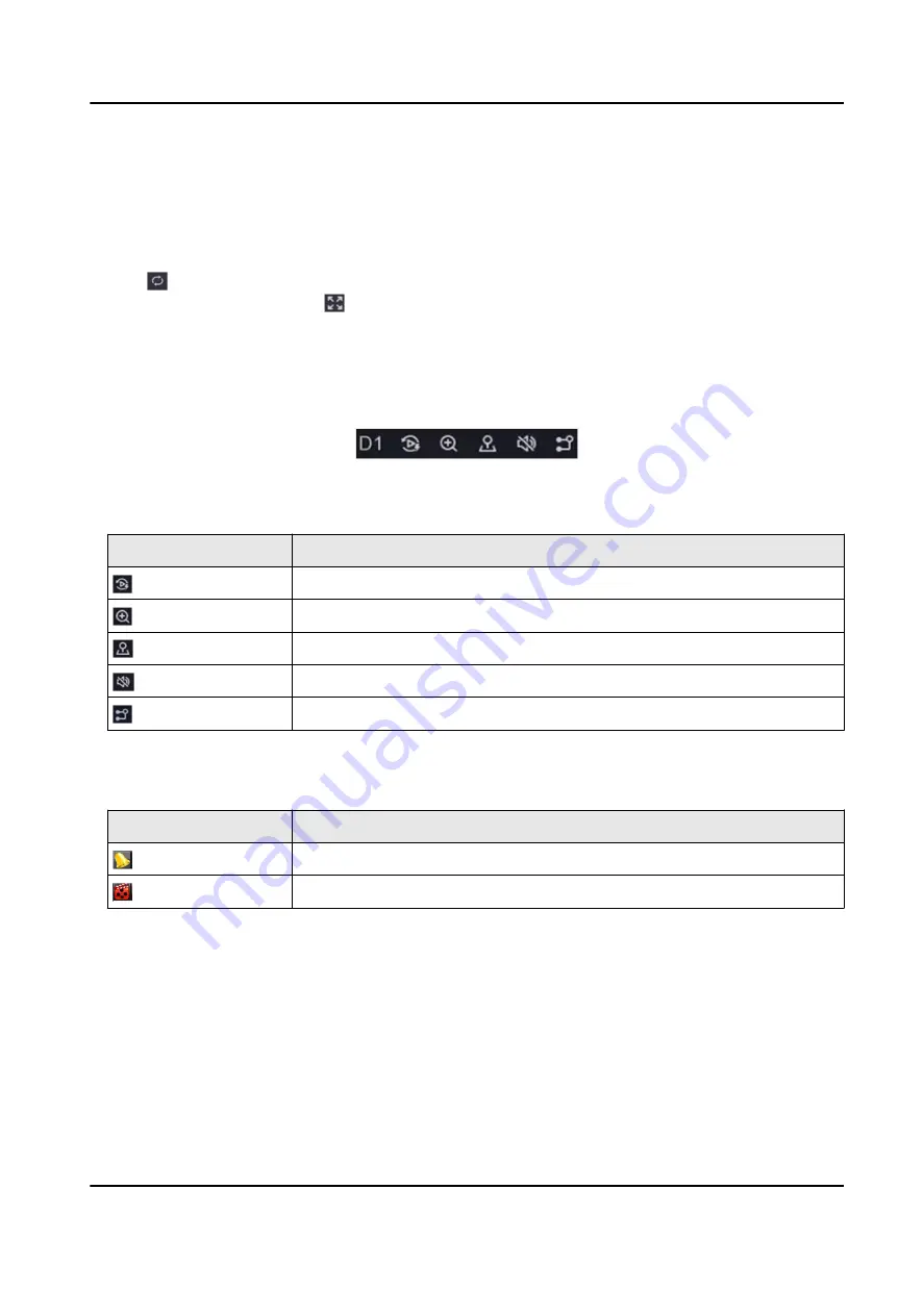
Position the cursor on a camera to show shortcut menu.

Figure 2-1 Shortcut Menu

Table 2-1 Shortcut Menu Description

Button

Description

Start playing videos recorded in the latest five minutes.
Digital zoom. You can adjust zoom-in times and view the desired area.
Click it to enter PTZ control mode.
Turn on/​off live view audio.
Switch video stream.

In the live view interface, there are icons at the upper-right corner of the screen for each

camera, showing the camera recording and alarm status.

Table 2-2 Live View Icon Description

Icon

Description

Alarming (normal event and smart event).
Recording.

Right click your mouse to display the shortcut menu.

2.2 PTZ Control

2.2.1 Configure PTZ Parameter

You shall configure PTZ parameters before controlling a PTZ camera.

Network Video Recorder User Manual

5

Summary of Contents for DS-7600NI-K1/4G Series

Page 1: ...Network Video Recorder User Manual ...

Page 2: ...OVIDED AS IS AND WITH ALL FAULTS AND ERRORS HIKVISION MAKES NO WARRANTIES EXPRESS OR IMPLIED INCLUDING WITHOUT LIMITATION MERCHANTABILITY SATISFACTORY QUALITY OR FITNESS FOR A PARTICULAR PURPOSE THE USE OF THE PRODUCT BY YOU IS AT YOUR OWN RISK IN NO EVENT WILL HIKVISION BE LIABLE TO YOU FOR ANY SPECIAL CONSEQUENTIAL INCIDENTAL OR INDIRECT DAMAGES INCLUDING AMONG OTHERS DAMAGES FOR LOSS OF BUSINES...

Page 3: ...ITED END USES INCLUDING THE DEVELOPMENT OR PRODUCTION OF WEAPONS OF MASS DESTRUCTION THE DEVELOPMENT OR PRODUCTION OF CHEMICAL OR BIOLOGICAL WEAPONS ANY ACTIVITIES IN THE CONTEXT RELATED TO ANY NUCLEAR EXPLOSIVE OR UNSAFE NUCLEAR FUEL CYCLE OR IN SUPPORT OF HUMAN RIGHTS ABUSES IN THE EVENT OF ANY CONFLICTS BETWEEN THIS MANUAL AND THE APPLICABLE LAW THE LATTER PREVAILS Network Video Recorder User M...

Page 4: ...y to correct the interference by one or more of the following measures Reorient or relocate the receiving antenna Increase the separation between the equipment and receiver Connect the equipment into an outlet on a circuit different from that to which the receiver is connected Consult the dealer or an experienced radio TV technician for help FCC Conditions This device complies with part 15 of the ...

Page 5: ...an Union See the product documentation for specific battery information The battery is marked with this symbol which may include lettering to indicate cadmium Cd lead Pb or mercury Hg For proper recycling return the battery to your supplier or to a designated collection point For more information see http www recyclethis info Industry Canada ICES 003 Compliance This device meets the CAN ICES 3 B N...

Page 6: ...del s Series Model DS 7600NI K1 4G DS 7604NI K1 4G DS 7608NI K1 4G DS 7600NI K1 P 4G DS 7604NI K1 4P 4G DS 7608NI K1 8P 4G DS 7600NI K2 4G DS 7608NI K2 4G DS 7616NI K2 4G DS 7600NI K2 P 4G DS 7608NI K2 8P 4G DS 7616NI K2 16P 4G Network Video Recorder User Manual v ...

Page 7: ...not avoided will or could result in death or serious injury Caution Indicates a potentially hazardous situation which if not avoided could result in equipment damage data loss performance degradation or unexpected results Note Provides additional information to emphasize or supplement important points of the main text Network Video Recorder User Manual vi ...

Page 8: ... device turn off the power at once and unplug the power cable and then please contact the service center Use the device in conjunction with an UPS and use factory recommended HDD if possible This product contains a coin button cell battery If the battery is swallowed it can cause severe internal burns in just 2 hours and can lead to death This equipment is not suitable for use in locations where c...

Page 9: ... certain models the equipment has been designed when required modified for connection to an IT power distribution system identifies the battery holder itself and identifies the positioning of the cell s inside the battery holder identifies the positive terminal s of equipment which is used with or generates direct current identifies the negative terminal s of equipment which is used with or genera...

Page 10: ...Parameter 5 2 2 2 PTZ Control Panel Introduction 7 2 2 3 Customize Preset 7 2 2 4 Customize Patrol 7 2 2 5 Customize Pattern 8 Chapter 3 Playback 9 3 1 GUI Introduction 9 3 2 Normal Playback 9 3 3 Event Playback 11 3 4 Back up Clip 12 Chapter 4 Search File 13 Chapter 5 Configuration Easy Mode 14 5 1 System Configuration 14 5 1 1 General 14 5 1 2 User 15 5 1 3 Exception 16 5 2 Network Configuration...

Page 11: ...guration 34 5 5 1 Configure Wireless Dial 34 5 5 2 Configure SMS 36 5 5 3 View Wireless Network Status 37 5 5 4 Data Monitoring 37 5 5 5 Configure Route Service 38 5 5 6 Upload Longitude and Latitude Info 38 5 6 Smart Encoding 39 5 6 1 Channel Zero Encoding 39 5 6 2 Configure Virtual Stream 40 Chapter 6 Configuration Expert Mode 43 6 1 System Configuration 43 6 1 1 General 43 6 1 2 Live View 45 6 ...

Page 12: ...66 6 4 3 Configure Arming Schedule 71 6 4 4 Configure Alarm Linkage Action 72 6 5 Recording Management 74 6 5 1 Configure Recording Schedule 74 6 5 2 Configure Recording Parameter 77 6 5 3 Storage Device 78 6 5 4 Configure Storage Mode 79 6 5 5 Advanced Settings 80 6 6 Wireless Configuration 81 6 6 1 Configure Wireless Dial 81 6 6 2 Configure SMS 82 6 6 3 View Wireless Network Status 83 6 6 4 Data...

Page 13: ...em Service 89 7 4 Upgrade 90 7 4 1 Local Upgrade 90 7 4 2 Online Upgrade 91 Chapter 8 Alarm 92 8 1 Set Event Hint 92 8 2 View Alarm in Alarm Center 92 Chapter 9 Web Operation 93 9 1 Introduction 93 9 2 Login 93 9 3 Live View 94 9 4 Playback 94 9 5 Configuration 95 9 6 Log 95 Chapter 10 Appendix 96 10 1 Glossary 96 10 2 Communication Matrix 97 10 3 Device Command 97 Network Video Recorder User Manu...

Page 14: ...ding at least three of the following categories upper case letters lower case letters numbers and special characters in order to increase the security of your product And we recommend you reset your password regularly especially in the high security system resetting the password monthly or weekly can better protect your product 4 Activate network camera s connected to the device Check Use the Devi...

Page 15: ...the mouse to draw a pattern among the 9 dots on the screen Release the mouse when the pattern is done Note The pattern shall have 4 dots at least Each dot can be connected for once only 2 Draw the same pattern again to confirm it When the two patterns match the pattern is configured successfully Figure 1 2 Set Unlock Pattern Network Video Recorder User Manual 2 ...

Page 16: ...otten your pattern you click Forgot My Pattern or Switch User to log in via password If you have drawn the wrong pattern for more than 5 times the system will switch to the normal login mode automatically 1 2 3 Log in via Password If your video recorder has logged out you must login before operating the menu and other functions Steps 1 Select User Name Network Video Recorder User Manual 3 ...

Page 17: ... 3 Click Login Note When you forget the password of the admin you can click Forgot Password to reset the password If you enter the wrong password 7 times the current user account will be locked for 60 seconds Network Video Recorder User Manual 4 ...

Page 18: ... 1 Shortcut Menu Description Button Description Start playing videos recorded in the latest five minutes Digital zoom You can adjust zoom in times and view the desired area Click it to enter PTZ control mode Turn on off live view audio Switch video stream In the live view interface there are icons at the upper right corner of the screen for each camera showing the camera recording and alarm status...

Page 19: ...a camera in live view and click on shortcut menu Figure 2 2 PTZ Settings 2 Click 3 Set the PTZ camera parameters Note All parameters should be the same as the PTZ camera 4 Click OK Network Video Recorder User Manual 6 ...

Page 20: ...w and click on shortcut menu 2 Select a desired preset in preset list 3 Use direction buttons to wheel the camera to required locations Adjust zoom and focus as your desire 4 Click What to do next Double click a preset in the preset list to call it 2 2 4 Customize Patrol Patrol refers to a path consists of a series of presets with designated sequence It provides dynamic live image for monitoring s...

Page 21: ...What to do next Select a patrol and click to call it The PTZ camera will move according the predefined patrol path 2 2 5 Customize Pattern A pattern records the movement path and dwell time in a certain position When you call a pattern the PTZ camera will move according to the recorded path Steps 1 Preview a camera in live view and click on shortcut menu 2 Click Pattern 3 Select a pattern 4 Click ...

Page 22: ... Full screen Start playback Speed down Speed up Speed Figure 3 2 Timeline Position the cursor on the timeline drag the timeline to position to a certain time Period marked with blue bar contains video Red bar indicates the video in the period is event video Scroll up down to zoom out in timeline 3 2 Normal Playback Play back normal videos Network Video Recorder User Manual 9 ...

Page 23: ...indow to show control bar Figure 3 3 Control Bar Table 3 2 Button Description Button Description Button Description Window division group the channels and play Zoom in out playback image Turn on off audio Add tag Lock unlock video Clip video Show videos that contain human Show videos that contain vehicle Skip Normal Videos If you have clicked the device will hide other videos and only show and pla...

Page 24: ...figuration Record Advanced Steps 1 Go to Playback 2 Click Event 3 Select a camera Figure 3 4 Event Playback 4 Position the cursor on playback window to show control bar Table 3 3 Button Description Button Description Button Description Add tag Zoom in out playback image Clip video Lock unlock video Configure detection area Turn on off audio 5 Click to set detection areas of line crossing detection...

Page 25: ... is enabled Figure 3 5 Play Strategy 3 4 Back up Clip You can clip videos during playback Video clips can be exported to the backup device USB flash drive etc Before You Start Connect a backup device to your video recorder Steps 1 Start playback Refer to Normal Playback for details 2 Click 3 Set the start and end time You can also adjust cursors on the time bar to set the time period 4 Click Save ...

Page 26: ...lect a search type video picture event etc 3 Set search conditions 4 Click Search Click to play the video Click to lock the file Locked file will not be overwritten Select file s and click Export to export file s to backup device Network Video Recorder User Manual 13 ...

Page 27: ...ion System General Figure 5 1 General Settings 2 Configure the parameters as your desire Wizard The wizard will pop up after the device starts up Lock Screen Password You need to enter your password if the screen is locked NTP Time Sync Network time protocol NTP is a networking protocol for time synchronization The device can connect to NTP network time protocol server to sync time Interval min Ne...

Page 28: ... password Figure 5 2 Add User 3 Enter user name 4 Enter the same password in Password and Confirm Warning We highly recommend you create a strong password of your own choosing Using a minimum of 8 characters including at least three of the following categories upper case letters lower case letters numbers and special characters in order to increase the security of your product And we recommend you...

Page 29: ...nterface 2 Click Next if you agree the Privacy Policy you can scan the QR code to read it 3 Follow the wizard to reset password 5 1 3 Exception You can receive exception events hint in alarm center and set exception linkage actions Steps 1 Go to Configuration System Exception 2 Optional Configure event hint When the set events occur you will receive hints in alarm center 1 Enable Event Hint 2 Clic...

Page 30: ...Configuration 5 2 1 General You shall properly configure the network settings before operating the device over network Steps 1 Go to Configuration Network General Figure 5 4 Network 2 Set network parameters DHCP Network Video Recorder User Manual 17 ...

Page 31: ...acy statement 2 Check I have read and agree to Service Terms and Privacy Statement if you agree with the service terms and privacy statement 3 Click OK 3 Click to set verification code 4 Optional Enable Platform Time Sync the device will sync time with the platform server instead of NTP server 5 Optional Enable Stream Encryption It requires to enter verification code in remote access and live view...

Page 32: ...Hik Connect platform Connection Status will be Online If your device is bound with a Hik Connect account Bind Status will be Yes What to do next You can access your video recorder via Hik Connect 5 2 3 Email Set an email account to receive event notification Before You Start Ensure SMTP service is available for your email Configure your network parameters Refer to General for details Steps 1 Go to...

Page 33: ... The password of email sender for SMTP server authentication SSL TLS Optional Enable SSL TLS if it is required by the SMTP server Attached Picture Optional If events are triggered it will send images as email attachment Sender The sender name Sender s Address The sender s email address Select Receiver Select a receiver Up to 3 receivers are available Receiver Network Video Recorder User Manual 20 ...

Page 34: ...ork camera is on the same network segment with your video recorder Ensure the network connection is valid and correct Refer to General for details Ensure the network camera password is the same as your video recorder Steps 1 Go to Configuration Camera IP Camera The online cameras on the same network segment with your video recorder are displayed in Online Device List Figure 5 7 IP Camera Managemen...

Page 35: ...mera is activated Steps 1 Go to Configuration Camera IP Camera 2 Click in Added Device List 3 Set network camera parameters including IP address protocol management port etc 4 Optional Enable Use Camera Activation Password to use the device password to add network camera s 5 Optional Click Add More to add another network camera 6 Click Add Figure 5 8 Add Network Camera Network Video Recorder User ...

Page 36: ... camera is on the same network segment with your video recorder Ensure the network connection is valid and correct Steps 1 Go to Configuration Camera IP Camera 2 Click 3 Click Yes to confirm 4 Select the camera upgrade firmware from your storage device 5 Click Upgrade to start upgrading The camera will restarted automatically after upgrade completed Configure Advanced Camera Parameters You can con...

Page 37: ...ure 5 9 OSD 3 Set parameters as your desire 4 Drag the text frames on the preview window to adjust the OSD position 5 Click Apply 5 3 3 Smart Event Motion Detection Motion detection enables the video recorder to detect the moving objects in the monitored area and trigger alarms Steps 1 Go to Configuration Camera Event Motion Detection Network Video Recorder User Manual 24 ...

Page 38: ...dily to triggers motion detection 6 Optional Set Target Detection as Human or Vehicle to discard alarms which are not triggered by human body or vehicle Only certain camera models support this function 7 Set the arming schedule Refer to Configure Arming Schedule for details 8 Set the linkage actions Refer to Configure Alarm Linkage Action for details 9 Click Apply Line Crossing Detection Line cros...

Page 39: ...to the A side can be detected 3 Set Sensitivity The higher the value is the easier the detection alarm will be triggered 4 Optional Set Target Detection as Human or Vehicle to discard alarms which are not triggered by human body or vehicle 5 Click Draw Area and set two points in the preview window to draw a virtual line 5 Set the arming schedule Refer to for Configure Arming Schedule for details 6...

Page 40: ...et Target Detection as Human or Vehicle to discard alarms which are not triggered by human body or vehicle 4 Click Draw Area to draw a quadrilateral detection region 5 Set the arming schedule Refer to for Configure Arming Schedule for details 6 Set the linkage actions Refer to Configure Alarm Linkage Action for details 7 Click Apply Region Entrance Detection Region entrance detection detects objec...

Page 41: ...Human or Vehicle to discard alarms which are not triggered by human body or vehicle 4 Click Draw Area to draw a quadrilateral detection region 5 Set the arming schedule Refer to for Configure Arming Schedule for details 6 Set the linkage actions Refer to Configure Alarm Linkage Action for details 7 Click Apply Region Exiting Detection Region exiting detection detects objects that exit from a prede...

Page 42: ...rd alarms which are not triggered by human body or vehicle 4 Click Draw Area to draw a quadrilateral detection region 5 Set the arming schedule Refer to for Configure Arming Schedule for details 6 Set the linkage actions Refer to Configure Alarm Linkage Action for details 7 Click Apply Configure Arming Schedule Steps 1 Select Arming Schedule 2 Choose one day of a week and set the time segment Up t...

Page 43: ...annel image when an alarm is triggered It requires to select the alarming channel s in Trigger Channel Buzzer Alarm It will trigger a buzzer beep when an alarm is triggered Notify Surveillance Center The device will send an exception or alarm signal to the remote client software when an alarm is triggered Send Email It will send an email with alarm information when an alarm is triggered PTZ Linkag...

Page 44: ...efore it can be used to save videos and information Before You Start Install at least an HDD to your video recorder For detailed steps refer to Quick Start Guide Steps 1 Go to Configuration Record Storage 2 Select an HDD 3 Click Init Repair Database Repair an HDD that with error in database Please operate it with the help of professional technical support Add Network Disk You can add the allocated...

Page 45: ...ontinuous main stream sub stream recording parameters for the camera Refer to Configure Recording Parameter for details 3 Go to Configuration Record Schedule 4 Select recording type as Continuous Refer to Edit Schedule for details Configure Event Recording You can configure the recording triggered by the motion detection line crossing detection and intrusion detection Steps 1 Go to Configuration E...

Page 46: ...n Enable 4 Configure the recording schedule Edit Schedule a Click Edit b Select a day to configure in Weekday c To set an all day recording schedule check All Day and select schedule type d To set other schedules uncheck All Day and set Start End Time and schedule type Note Up to 8 periods can be configured for each day And the time periods cannot be overlapped with each other e Click OK to save t...

Page 47: ...ame Rate Frame rate refers to how many frames are captured each second A higher frame rate is advantageous when there is movement in the video stream as it maintains image quality throughout Resolution Image resolution is a measure of how much detail a digital image can hold the greater the resolution the greater the level of detail Resolution can be specified as the number of pixel columns width ...

Page 48: ...Edit 3 Select a day of the week 4 Set the online period for the day Up to 8 periods are allowed for a day 5 Set the online period for other days You can click Copy to copy the period to other days 6 Click OK 6 Set keep alive parameters A keep alive KA is a message sent by one device to another to check that the link between the two is operation or to prevent the link from being broken 1 Enable kee...

Page 49: ...mmands to control the wireless dial related functions Table 5 1 SMS Self service Text Message Description Text Message Description 101 Enable wireless dial 102 Disable wireless dial 103 Get dial status 201 Enable SMS alarm linkage action 202 Disable SMS alarm linkage action 3 Click Add to add a SMS user 1 Enter a user name in User Name 2 Turn on Enable SMS Alarm Function When SMS alarm linkage act...

Page 50: ...ckage data limit in Package Data 3 If Package Type is set as Month Package set the start time of your month data package 4 Select an option for Data Limit Notification Turn Off Data and Notify When the data usage exceeds the limit the device will turn off wireless dial and notify you Only Notify When the data usage exceeds the limit the device will notify you but keep wireless dial on 5 Set the no...

Page 51: ...her video recorder and set its gateway IP address The gateway IP address is the wired LAN IP address of your wireless network video recorder You can go to Configuration Network General TCP IP to view the IP address of your wireless network video recorder Note You can repeat the above steps to add other video recorders 7 Click Apply 5 5 6 Upload Longitude and Latitude Info After the GPS module opti...

Page 52: ...ero encoding refers to local output encoding for network transmission In order to decrease the bandwidth requirement without affecting the image quality channel zero encoding provides a combined live image of multiple channels Users can view the videos from channel zero remotely Division capacity is depended on output videos and bandwidth on upper bitrate limit Go to Configuration Smart Encoding C...

Page 53: ...ghout Max Bitrate The maximum bit rate of coding theory The reference value of video encoding 5 6 2 Configure Virtual Stream In order to save wireless data and bandwidth remote live view sub stream or remote playback video stream can be transcoded to vitrual stream Steps 1 Go to Configuration Smart Encoding Virtual Stream 2 Select Transcoded Live View or Transcoded Playback according to your requi...

Page 54: ...he maximum bit rate of coding theory The reference value of video encoding Figure 5 25 General Parameters Note Virtual stream can only transcode remote live view sub stream or remote playback video stream The number of virtual stream channels is limited When the virtual stream transcoding capability is not enough remote live view sub stream or remote playback video stream would still be the origin...

Page 55: ...sion The interested region would be assigned with more encoding resource to lossless compression while the background information will be showed in lossy compression 1 Click Advanced Settings 2 Enable ROI 3 Select an area 4 Click Draw Area to draw an area on the preview image 7 Click Apply Network Video Recorder User Manual 42 ...

Page 56: ...lution which must be the same with the resolution of the VGA HDMI display Lock Screen Password You need to enter password for authentication if the screen is locked Mouse Pointer Speed Set the speed of mouse pointer 4 levels are configurable Wizard The wizard will pop up after the device starts up Enhanced SVC Mode Scalable Video Coding SVC is an extension of the H 264 and H 265 standard When the ...

Page 57: ...n the evening during months when the weather is the warmest Go to Configuration System General DST Settings configure the parameters as your desire and click Apply Figure 6 2 DST Settings Configure More Settings You can configure your device name lock screen time output mode etc Go to Configuration System General More Settings configure the parameters as your desire and click Apply Network Video R...

Page 58: ...s from 1 to 255 and the default value is 255 Lock Screen Set timeout time for lock screen Menu Output Mode Choose output to display local menu Figure 6 3 More Settings 6 1 2 Live View Configure General Parameters You can configure the output interface mute or turning on the audio event output interface etc Steps 1 Go to Configuration System Live View General Network Video Recorder User Manual 45 ...

Page 59: ... show alarm event image Audio Turn on off audio output for the selected video output Volume Adjust the live view playback and two way audio volume for the selected video output interface 3 Click Apply Configure Live View Layout Steps 1 Go to Configuration System Live View View 2 Set Output Interface 3 Select a window and double click a camera the list you would like to display means no camera is d...

Page 60: ...terface as Channel Zero 3 Go to Configuration System Live View Channel Zero Figure 6 5 Channel Zero 4 Turn on Enable 5 Configure Frame Rate Max Bitrate Mode and Max Bitrate The higher frame rate and bitrate require higher bandwidth requirement 6 Click Apply 6 1 3 User Refer to User for details 6 2 Network Configuration 6 2 1 TCP IP TCP IP must be properly configured before you operate video record...

Page 61: ...al bandwidth which enables the system to provide two Gigabit network capacity Note Working mode is only available for certain models NIC Type Select NIC type as your desire DHCP If the DHCP server is available you can check Enable DHCP to automatically obtain an IP address and other network settings from that server MTU The maximum transmission unit MTU is the size of the largest network layer pro...

Page 62: ...or port mapping to realize the remote access via the cross segment network UPnP and manual mapping Before You Start Enable the UPnP function of your router if UPnP is required When the device network working mode is multi address the default device route should be on the same network segment as the LAN IP address of the router Steps 1 Go to Configuration Network General NAT Network Video Recorder ...

Page 63: ...ports should be between 1 and 65535 and the value must be different from each other If multiple devices are configured for the UPnP settings under the same router the value of the port No for each device should be unique 4 Set the virtual server of your router including internal source port external source port etc The virtual server parameters shall be corresponding with your device port 6 2 4 NT...

Page 64: ...80 Multicast IP Multicast can be configured to enable live view for cameras that exceed the maximum number allowed through network A multicast IP address covers Class D IP ranging from 224 0 0 0 to 239 255 255 255 and it is recommended to use the IP address ranging from 239 252 0 0 to 239 255 255 255 When adding a device to the CMS software the multicast address must be the same as that of the dev...

Page 65: ...arty platform to access devices such as NVRs speed domes DVRs network cameras mobile NVRs mobile devices decoding devices etc With this protocol the third party platform can realize functions like live view playback two way audio PTZ control etc Steps 1 Go to Configuration Network Platform Access 2 Set Type as ISUP Network Video Recorder User Manual 52 ...

Page 66: ...all be provided by the platform Version ISUP protocol version only V5 0 is available Encryption Password Encryption password is required when using ISUP V5 0 version it provides more secure communication between the device and platform Enter it for verification after the device is registered to the ISUP platform 5 Click Apply to save the settings and restart the device What to do next You can see ...

Page 67: ...network camera is on the same network segment with your video recorder Ensure the network connection is valid and correct Ensure the network camera password is the same as your video recorder Steps 1 Go to Configuration Camera Camera IP Channel 2 Click Online Device List The online cameras on the same network segment will be displayed in the list Figure 6 10 Online Device 3 Select a network camera...

Page 68: ...Go to Configuration Camera Camera IP Channel 2 Click Figure 6 11 Add IP Camera 3 Enter network camera parameters Use Channel Default Password If it is enabled the video recorder will add the camera by the set channel default password 4 Click Add Edit Connected Network Camera You can edit the IP address protocol and other parameters of the added network cameras Network Video Recorder User Manual 55...

Page 69: ...recorder Ensure the network connection is valid and correct Steps 1 Go to Configuration Camera Camera IP Channel 2 Click 3 Click Yes to confirm 4 Select the camera upgrade firmware from your storage device 5 Click Upgrade to start upgrading The camera will restarted automatically after upgrade completed Configure Advanced Camera Parameters You can configure advanced camera parameters like camera I...

Page 70: ...0 meters network transmissions via PoE interface Short Distance Short distance 100 meters network transmission via PoE interface Note The PoE ports are enabled with the short distance mode by default The bandwidth of IP camera connected to the PoE via long network cable 100 to 300 meters cannot exceed 6 Mbps The allowed max long network cable may be less than 300 meters depending on different IP c...

Page 71: ...camera Steps 1 Go to Configuration Camera Camera IP Channel 2 Click of a channel with no linked network camera 3 Select Adding Method as Manual Plug and Play The camera is physically connected to the PoE interface You can click in the added device list to edit its parameters Manual Add IP camera without physical connection via network cable 4 Set other parameters such as user name password and IP ...

Page 72: ...nect a backup device such as a USB flash drive to your video recorder Steps 1 Go to Configuration Camera Camera IP Channel 2 Click Export Import to export import configuration files to the connected backup device 3 Set the storage device and folder path 4 Click Export Import What to do next After the importing process is completed you must restart the video recorder Advanced Settings Steps 1 Go to...

Page 73: ...e OSD Settings Configure the OSD On screen Display settings for the camera including date time camera name etc Image Settings Customize the image parameters including the brightness contrast and saturation for the live view and recording effect Exposure Set the camera exposure time 1 10000 to 1 sec A larger exposure value results in a brighter image Day Night Switch The camera can be set to day ni...

Page 74: ...o adjust the OSD position 5 Click Apply 6 3 3 Privacy Mask You are allowed to configure the privacy mask areas that cannot be viewed or recorded Steps 1 Go to Configuration Camera Privacy Mask 2 Select Camera 3 Turn on Enable Network Video Recorder User Manual 61 ...

Page 75: ...e of each area can be adjusted 5 Click Apply 6 4 Event Configuration 6 4 1 Normal Event Motion Detection Motion detection enables the video recorder to detect the moving objects in the monitored area and trigger alarms Refer to Motion Detection for details Video Tampering Trigger alarm when the lens is covered and take alarm response actions Network Video Recorder User Manual 62 ...

Page 76: ...o Configure Alarm Linkage Action for details 7 Click Apply Video Loss Detect video loss of a camera and take alarm response actions Steps 1 Go to Configuration Event Normal Event Video Loss 2 Set Camera 3 Turn on Enable 4 Set the arming schedule Refer to Configure Arming Schedule for details 5 Set the linkage actions Refer to Configure Alarm Linkage Action for details 6 Click Apply Alarm Input Set...

Page 77: ...s Nonuse the alarm input will be disabled If you set Settings as One Key Disarmig the selected linkage method s of the alarm input will be disabled 6 Set the arming schedule Refer to Configure Arming Schedule for details 7 Set the linkage actions Refer to Configure Alarm Linkage Action for details 8 Click Apply Alarm Output Trigger an alarm output when an alarm is triggered Steps 1 Go to Configura...

Page 78: ...gger alarm outputs and linkage actions Steps 1 Go to Configuration Event Normal Event Exception 2 Configure event hint When the set events occur you will receive hints in alarm center 1 Enable Event Hint 2 Select events to hint Choose from Click of Event Hint Configuration to select events Click in the upper right corner of local menu to enter alarm center to select events 3 Select Exception Type ...

Page 79: ...2 Smart Event Line Crossing Detection Line crossing detection detects people vehicles and objects crossing a set virtual line The detection direction can be set as bidirectional from left to right or from right to left Steps 1 Go to Configuration Event Smart Event Line Crossing Network Video Recorder User Manual 66 ...

Page 80: ...y an object crossing the configured line from the A side to the B side can be detected B A Only an object crossing the configured line from the B side to the A side can be detected 3 Optional Set Target Detection as Human or Vehicle to discard alarms which are not triggered by human body or vehicle 4 Click Draw Area and draw a quadrilateral in the preview window by specifying four vertexes of the ...

Page 81: ...e of the object that can trigger the alarm The higher the value is the more easily the detection alarm will be triggered Its range is 1 100 Time Threshold Range 1s 10s the threshold for the time of the object loitering in the region When the duration of the object in the defined detection area is longer than the set time the alarm will be triggered 3 Optional Set Target Detection as Human or Vehic...

Page 82: ...he captured pictures of VCA detection 5 Set the detection rules and detection areas 1 Set Arming Area Up to 4 arming areas are selectable 2 Adjust Sensitivity Sensitivity Range 0 100 The higher the value is the more easily the detection alarm can be triggered 3 Optional Set Target Detection as Human or Vehicle to discard alarms which are not triggered by human body or vehicle 4 Click Draw Area and...

Page 83: ... rules and detection areas 1 Set Arming Area Up to 4 arming areas are selectable 2 Adjust Sensitivity Sensitivity Range 0 100 The higher the value is the more easily the detection alarm can be triggered 3 Optional Set Target Detection as Human or Vehicle to discard alarms which are not triggered by human body or vehicle 4 Click Draw Area and draw a quadrilateral in the preview window by specifying...

Page 84: ...on Event Smart Event 2 Select a thermal camera detection event 3 Set Camera 4 Set the arming schedule Refer to Configure Arming Schedule for details 5 Set the linkage actions Refer to Configure Alarm Linkage Action for details 6 Click Apply 6 4 3 Configure Arming Schedule Steps 1 Click Arming Schedule 2 Choose one day of a week and set the time segment Up to eight time periods can be set within ea...

Page 85: ...nds default dwell time 3 Go to Linkage Action interface of the alarm detection 4 Select Full Screen Monitoring alarm linkage action 5 Select the channel s in Trigger Channel settings you want to make full screen monitoring Note Auto switch will terminate once the alarm stops and back to the live view interface Configure Audio Warning The audio warning enables the video recorder to trigger an audib...

Page 86: ...can be triggered by the normal and smart events Steps 1 Go to Linkage Action interface of the alarm input or event detection 2 Click Trigger Alarm Output 3 Select the alarm outputs to trigger 4 Go to Configuration Event Normal Event Alarm Output 5 Select an alarm output item from the list Refer to Alarm Output for details Configure PTZ Linkage Video recorder can trigger the PTZ actions e g call pr...

Page 87: ...elect audio or light as your desire 3 Click Apply Note If you require to set audio and light parameters please log into the network camera via web browser to configure them 6 5 Recording Management 6 5 1 Configure Recording Schedule Video recorder will automatically start stop recording according to the configured schedule Configure Continuous Recording Steps 1 Go to Configuration Record Parameter...

Page 88: ...iguration Record Schedule 6 Select recording type as Event Edit Schedule Steps 1 Go to Configuration Record Schedule Figure 6 28 Recording Schedule Continuous Continuous recording Event Recording triggered by all event triggered alarms 2 Select a camera in Camera No 3 Turn on Enable 4 Configure the recording schedule 1 Click Edit 2 Select a day to configure in Weekday 3 To set an all day recording...

Page 89: ...ords at 9 59 55 Post Record The time you set to record after the event or the scheduled time For example when an alarm triggered recording ends at 11 00 and if you set the post record time as 5 seconds it records till 11 00 05 Stream Type Main stream and sub stream are selectable for recording When you select sub stream you can record for a longer time with the same storage space Video Picture Exp...

Page 90: ...w live video Users with limited internet speeds may benefit most from this setting Frame Rate Frame rate refers to how many frames are captured each second A higher frame rate is advantageous when there is movement in the video stream as it maintains image quality throughout Resolution Image resolution is a measure of how much detail a digital image can hold the greater the resolution the greater ...

Page 91: ...DD 3 Click Init Add Network Disk You can add the allocated NAS or IP SAN disk to the video recorder and use it as a network HDD Steps 1 Go to Configuration Record Storage 2 Click Add 3 Set NetHDD 4 Set Type as NAS or IPSAN 5 Enter NetHDD IP address 6 Click to search the available disks Figure 6 30 Add NetHDD 7 Select NAS disk from the list or manually enter the directory in NetHDD Directory 8 Clic...

Page 92: ...is function is only available for certain models 1 Go to Configuration Record Storage Mode 2 Select Mode as Group 3 Select a group number 4 Select IP cameras to record on the HDD group Figure 6 31 Group 5 Click Apply 6 Restart the video recorder to activate the new storage mode settings 7 After restart go to Configuration Record Storage 8 Click of desired HDD to set the group 9 Select a group numb...

Page 93: ...as will use the total capacity of HDD for videos and pictures 5 Click Apply 6 Restart the video recorder to activate the new settings 6 5 5 Advanced Settings Steps 1 Go to Configuration Record Advanced 2 Configure the parameters as your desire Overwrite Disable When the HDD is full video recorder will stop writing Enable When hard drive is full video record will continue to write new files by dele...

Page 94: ...nfigure Wireless Dial Access to 3G or 4G wireless network via wireless dial Before You Start Ensure the SIM UIM card and antenna are properly installed to your device Ensure your SIM UIM card is valid Steps 1 Go to Configuration Wireless Dial Settings Figure 6 33 Wireless Dial 2 Turn on Enable Dial 3 Optional Turn on Enable 4G to enable 4G network The device will use 3G if Enable 4G is unchecked 4...

Page 95: ... keep alive transmission is not received 3 Enter server IP address in Server 4 Click Test to test if the settings are valid 7 Click Apply 6 6 2 Configure SMS When SMS alarm linkage action is enabled the device will send a text message to a cellphone user if an alarm is detected Moreover the SMS self service enables you to send text messages as commands to turn on off wireless dial view dial status...

Page 96: ... Delete to edit delete the selected user 5 Click Apply 6 6 3 View Wireless Network Status Go to Configuration Wireless Dial Status to view SIM UIM card status network parameters etc 6 6 4 Data Monitoring You can monitor your data usage and set the data package limit and data warning limit in case your data usage exceeds the limit Steps 1 Go to Configuration Wireless Data Monitoring Figure 6 35 Dat...

Page 97: ...ly 6 6 5 Configure Route Service The device can be used as a router to share its wireless network with other video recorder s Before You Start Ensure the wireless dial function is properly configured and the wireless network is accessible Ensure other video recorder s are on the same network segment with your video recorder Steps 1 Go to Configuration Wireless Route Settings Figure 6 36 Rout Setti...

Page 98: ... Start The GPS module is optional be sure the GPS module is properly connected to the ANT interface at rear panel Steps 1 Go to Configuration Wireless Longitude and Latitude Info Figure 6 37 Upload Longitude and Latitude Info 2 Check Enable Upload 3 Set Upload Interval Upload Interval The device will automatically upload longitude and latitude information to the platform according to the time inte...

Page 99: ...ision capacity is depended on output videos and bandwidth on upper bitrate limit Go to Configuration Smart Encoding Channel Zero to enable the function and configure parameters Figure 6 38 Channel Zero Encoding Enhanced SVC Mode Enhanced SVC mode extracts video frames to provide better decoding capacity Frame Rate It refers to the number of frames captured each second A higher frame rate is advant...

Page 100: ...e View or Transcoded Playback according to your requirement 3 Select a camera 4 Turn on Enable 5 Configure general parameters Enhanced SVC Mode Enhanced SVC mode extracts video frames to provide better decoding capacity Frame Rate It refers to the number of frames captured each second A higher frame rate is advantageous when there is movement in the video stream as it maintains image quality throu...

Page 101: ... original stream 6 Optional Configure region of interest ROI ROI ROI is an encoding technology which helps to discriminate the interested region and the background information in video compression The interested region would be assigned with more encoding resource to lossless compression while the background information will be showed in lossy compression 1 Click Advanced Settings 2 Enable ROI 3 S...

Page 102: ...s and leave all settings unchanged except restoring user accounts 3 Click Yes The device will reboot automatically 7 2 Search Log The operation alarm exception and information of video recorder can be stored in logs which can be viewed and exported at any time Steps 1 Click at the upper right corner 2 Click More 3 Click Log Information 4 Set the search conditions 5 Click Search 7 3 System Service ...

Page 103: ...I and ONVIF will terminate as well HTTP Authentication If you need to enable the HTTP service you can set the HTTP authentication to enhance the access security Two authentication types are selectable For security reasons it is recommended to select digest as the authentication type Camera Added Detection The function detects the network camera status If the network camera has been added by anothe...

Page 104: ...lick at the upper right corner 2 Click 3 Go to Online Upgrade 4 Download the latest firmware Auto Download The will automatically check and download the latest firmware Test Upgrade Click Test Upgrade to manually check and download the latest firmware 5 Upgrade your device if a new firmware version is available The device will reboot automatically Network Video Recorder User Manual 91 ...

Page 105: ... Smart Event as your desire Figure 8 1 Alarm Center 3 Click and select events to hint 4 Click OK When the selected events occur the alarm information will be displayed in locating at the upper right corner of local menu 8 2 View Alarm in Alarm Center Steps 1 Click at the upper right corner of local menu 2 Click Exception Basic Event or Smart Event to view as your desire Network Video Recorder User...

Page 106: ...mponents exe 9 2 Login You shall acknowledge that the use of the product with Internet access might be under network security risks For avoidance of any network attacks and information leakage please strengthen your own protection If the product does not work properly please contact with your dealer or the nearest service center Steps 1 Open web browser input the IP address of the video recorder a...

Page 107: ...browser to finish the installation of the plug in 9 3 Live View After login live view interface shows Figure 9 2 Live View 9 4 Playback Click Playback to enter playback interface Figure 9 3 Playback Network Video Recorder User Manual 94 ...

Page 108: ... Configuration to enter configuration interface Figure 9 4 Configuration 9 6 Log Steps 1 Go to Maintenance System Maintenance Log 2 Set the search conditions 3 Click Search Figure 9 5 Log Network Video Recorder User Manual 95 ...

Page 109: ... network HTTP Acronym for Hypertext Transfer Protocol A protocol to transfer hypertext request and information between servers and browsers over a network PPPoE PPPoE Point to Point Protocol over Ethernet is a network protocol for encapsulating Point to Point Protocol PPP frames inside Ethernet frames It is used mainly with ADSL services where individual users connect to the ADSL transceiver modem...

Page 110: ...standard used in broadcast televisions systems in large parts of the world PAL signal contains 625 scan lines at 50Hz PTZ Acronym for Pan Tilt Zoom PTZ cameras are motor driven systems that allow the camera to pan left and right tilt up and down and zoom in and out USB Acronym for Universal Serial Bus USB is a plug and play serial bus standard to interface devices to a host computer 10 2 Communica...

Page 111: ...Figure 10 2 Device Command Network Video Recorder User Manual 98 ...

Page 112: ...UD29505B ...

Reviews: