background image

Network Video Recorder User Manual 

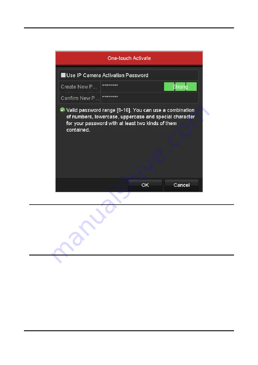
If IP Camera Activation Password is not used, you shall create a new password for the 
camera. 


Figure 1-7 Set New Password 

Warning 
Strong Password recommended–We highly recommend you create a strong password of your 
own choosing (Using a minimum of 8 characters, including at least three of the following 
categories: upper case letters, lower case letters, numbers, and special characters.) in order to 
increase the security of your product. And we recommend you reset your password regularly, 
especially in the high security system, resetting the password monthly or weekly can better 
protect your product. 


4. Click OK

The security status of camera will be changed to Active

1.2.2 Add Wi-Fi Cameras 

You can use Wi-Fi match function to search Wi-Fi cameras that are not activated, and add them to 
the device automatically. 
Select Wi-Fi Match from the right-click menu in live view mode, and the device will search and add 

Summary of Contents for DS-7100NI-K1/W/M Series

Page 1: ...Network Video Recorder User Manual ...

Page 2: ... FOR ANY SPECIAL CONSEQUENTIAL INCIDENTAL OR INDIRECT DAMAGES INCLUDING AMONG OTHERS DAMAGES FOR LOSS OF BUSINESS PROFITS BUSINESS INTERRUPTION OR LOSS OF DATA CORRUPTION OF SYSTEMS OR LOSS OF DOCUMENTATION WHETHER BASED ON BREACH OF CONTRACT TORT INCLUDING NEGLIGENCE PRODUCT LIABILITY OR OTHERWISE IN CONNECTION WITH THE USE OF THE PRODUCT EVEN IF OUR COMPANY HAS BEEN ADVISED OF THE POSSIBILITY OF...

Page 3: ...Network Video Recorder User Manual ii RIGHTS ABUSES IN THE EVENT OF ANY CONFLICTS BETWEEN THIS MANUAL AND THE APPLICABLE LAW THE LATER PREVAILS ...

Page 4: ...terference by one or more of the following measures Reorient or relocate the receiving antenna Increase the separation between the equipment and receiver Connect the equipment into an outlet on a circuit different from that to which the receiver is connected Consult the dealer or an experienced radio TV technician for help FCC Conditions This device complies with part 15 of the FCC Rules Operation...

Page 5: ...rouillage et 2 l utilisateur de l appareil doit accepter tout brouillage radioélectrique subi même si le brouillage est susceptible d en compromettre le fonctionnement Under Industry Canada regulations this radio transmitter may only operate using an antenna of atype and maximum or lesser gain approved for the transmitter by Industry Canada To reducepotential radio interference to other users the ...

Page 6: ...er Manual v Applicable Model This manual is applicable to the following models Table 1 1 Applicable Model Series Model DS 7100NI K1 W M DS 7104NI K1 W M DS 7108NI K1 W M DS 7100NI K1 W M C DS 7104NI K1 W M C DS 7108NI K1 W M C ...

Page 7: ...icates a hazardous situation which if not avoided will or could result in death or serious injury Caution Indicates a potentially hazardous situation which if not avoided could result in equipment damage data loss performance degradation or unexpected results Note Provides additional information to emphasize or supplement important points of the main text ...

Page 8: ...tion Input voltage should meet both the SELV Safety Extra Low Voltage and the Limited Power Source with 100 VAC to 240 VAC or 12 VDC according to the IEC60950 1 standard Please refer to technical specifications for detailed information Do not connect several devices to one power adapter as adapter overload may cause over heating or a fire hazard Please make sure that the plug is firmly connected t...

Page 9: ...ay cause damage to the sensitive electronics within the recorder Use the device in conjunction with an UPS if possible Power down the recorder before connecting and disconnecting accessories and peripherals A factory recommended HDD should be used for this device Improper use or replacement of the battery may result in hazard of explosion Replace with the same or equivalent type only Dispose of us...

Page 10: ... 11 1 2 6 Edit the Connected IP Cameras and Configure Customized Protocols 11 1 3 Configure Guarding Vision 14 Chapter 2 Camera Settings 16 2 1 Configure OSD Settings 16 2 2 Configure Privacy Mask 16 2 3 Configure Video Parameters 17 Chapter 3 Live View 19 3 1 Introduction of Live View 19 3 2 Operations in Live View Mode 19 3 2 1 Use the Mouse in Live View 20 3 2 2 Use an Auxiliary Monitor 22 3 2 ...

Page 11: ...ock the Recording Files 55 4 9 2 Set HDD Property to Read only 57 Chapter 5 Playback 59 5 1 Play Back Record Files 59 5 1 1 Instant Playback 59 5 1 2 Play Back by Normal Search 60 5 1 3 Play Back by Smart Search 60 5 1 4 Play Back by Event Search 61 5 1 5 Play Back by Tag 62 5 1 6 Play Back by System Logs 64 5 1 7 Play Back External File 66 5 1 8 Play Back by Sub periods 66 5 2 Auxiliary Functions...

Page 12: ...ns 86 7 8 1 Trigger Alarm Output 87 7 9 Trigger or Clear Alarm Output Manually 89 Chapter 8 Network Settings 90 8 1 Configure General Settings 90 8 2 Configure Wi Fi 90 8 3 Configure Advanced Settings 92 8 3 1 Configuring DDNS 92 8 3 2 Configure NTP Server 92 8 3 3 Configure More Settings 92 8 3 4 Configure Email 93 8 3 5 Configuring NAT 95 8 4 Check Network Traffic 96 8 5 Configure Network Detect...

Page 13: ...1 Upgrade by Local Backup Device 114 10 8 2 Upgrade by FTP 115 10 9 Reset Password by GUID 116 10 10 Restore Default Settings 116 Chapter 11 Appendix 118 11 1 Glossary 118 11 2 Frequently Asked Questions 119 11 2 1 Why is there a part of channels displaying No Resource or turning black screen in multi screen of live view 119 11 2 2 Why is the video recorder notifying not support the stream type 12...

Page 14: ...corder notifying IP conflict 122 11 2 10 Why is image getting stuck when the video recorder is playing back by single or multi channel cameras 122 11 2 11 Why does my video recorder make a beeping sound after booting 122 11 2 12 Why is there no recorded video after setting the motion detection 122 11 2 13 Why is the sound quality not good in recording video 123 ...

Page 15: ...ruptible Power Supply UPS is used in conjunction with the device Press the power button on the panel The power indicator LED would be lighted up which indicating the device begins to start up Shut Down Your Device Go to Menu Shutdown Click Shutdown and click Yes If your device has a power button on the front panel you can also hold the power button for 3 seconds and then enter the admin user name ...

Page 16: ...aracters including at least three of the following categories upper case letters lower case letters numbers and special characters in order to increase the security of your product And we recommend you reset your password regularly especially in the high security system resetting the password monthly or weekly can better protect your product Figure 1 2 Set Admin Password 2 Check Use Device Passwor...

Page 17: ... 1 3 Login For the admin if you have entered the wrong password for 7 times the account will be locked for 60 seconds For the operator if you have entered the wrong password for 5 times the account will be locked for 60 seconds User Logout After logging out the monitor turns to the live view mode and if you want to perform any operations you need to enter user name and password log in again Go to ...

Page 18: ...ps 1 Use mouse to draw a pattern among the 9 dots on the screen Release the mouse when the pattern is done Figure 1 5 Set Unlock Pattern Note The pattern shall have 4 dots at least Each dot can be connected for once only 2 Draw the same pattern again to confirm it Note You can go to Menu Configuration User and click to edit or disable the unlock pattern ...

Page 19: ...ra detected online in the same network segment the Password status shows whether it is active or inactive Figure 1 6 IP Camera Management Interface 2 Click the inactive icon of the camera to enter the following interface to activate it You can also select multiple cameras from the list and click the One touch Activate to activate the cameras in batch 3 Set the password of the camera to activate it...

Page 20: ...wer case letters numbers and special characters in order to increase the security of your product And we recommend you reset your password regularly especially in the high security system resetting the password monthly or weekly can better protect your product 4 Click OK The security status of camera will be changed to Active 1 2 2 Add Wi Fi Cameras You can use Wi Fi match function to search Wi Fi...

Page 21: ...nline IP Cameras The main function of the NVR is to connect the network cameras and record the video got from it So before you can get a live view or record of the video you should add the network cameras to the connection list of the device Before You Start Ensure the network connection is valid and correct For detailed checking and configuring of the network Steps 1 Adding the IP Cameras OPTION ...

Page 22: ...ick Menu Camera Camera to enter the IP camera management interface Figure 1 9 Adding IP Camera Interface 2 The online cameras with same network segment will be detected and displayed in the camera list 3 Select the IP camera from the list and click the button to add the camera Or you can click the One touch Adding button to add all cameras with the same login password from ...

Page 23: ...ders with multiple channels only check the Channel Port checkbox in the pop up window as shown in the following figure and click OK to add multiple channels Figure 1 10 Selecting Multiple Channels OPTION 3 1 On the IP Camera Management interface click the Custom Adding button to pop up the Add IP Camera Custom interface ...

Page 24: ...dd other IP cameras 4 Click Addto add the camera The successfully added cameras are listed in the interface Table 1 1 Description of Icons Icon Description Icon Description Edit basic parameters of the camera Add the detected IP camera The camera is disconnected you can click the icon to get the exception information of camera Delete the IP camera Play the live video of the connected camera Advanc...

Page 25: ...e show the passwords of the successfully added IP cameras in the list You must enter the admin password to confirm permission 1 2 6 Edit the Connected IP Cameras and Configure Customized Protocols After the adding of the IP cameras the basic information of the camera lists in the page you can configure the basic setting of the IP cameras Steps 1 Click to edit the parameters you can edit the IP add...

Page 26: ...ck Figure 1 13 Paramerters Configuration of the Camera 2 You can edit the network information and the password of the camera 3 Click OK to save the settings and exit the interface Note To connect the network cameras which are not configured with the standard protocols you can configure the customized protocols for them 4 Configuring the customized protocols 1 Click Protocol in the custom adding IP...

Page 27: ...rk camera to consult the URL uniform resource locator for getting main stream and sub stream The format of the URL is Type IP Address of the network camera Port Path Example rtsp 192 168 1 55 554 ch1 main av_stream Protocol Name Edit the name for the custom protocol Enable Substream If the network camera does not support sub stream or the sub stream is not needed leave the checkbox empty Type The ...

Page 28: ...ng Vision provides mobile phone application and platform service to access and manage your connected devices which enables you to get a convenient remote access to the surveillance system Steps 1 Go to Menu Configuration Network Platform Access 2 Check Enable The service terms will pop up 1 Enter the verification code in Verification Code 2 Scan the QR code to read the service terms and privacy st...

Page 29: ... Optional Check Custom to enter the server address as your desire 4 Optional Check Enable Stream Encryption verification code is required for remote access and live view 5 Optional Click Unbind if the device requires to unbind with the current Guarding Vision account 6 Click Apply What to do next After configuration you can access and manage your devices through Guarding Vision app or website ...

Page 30: ... Edit Camera Name 4 Select Display Name Display Date or Display Week as your desire 5 Set Date Format Time Format and Display Mode Figure 2 1 OSD Configuration 6 Drag the text frame on the preview window to adjust its position 7 Click Apply 2 2 Configure Privacy Mask You can customize the image parameters including the brightness contrast saturation image rotate and mirror for the live view and re...

Page 31: ...ct Mirror ModetoLeft Right Up Down Center or OFF When OFF is selected the image is restored to original Note The Rotate and Mirror functions must be supported by the connected IP camera The image parameters adjustment can affect both the live view and the recording quality 6 Click Apply 2 3 Configure Video Parameters You can customize the image parameters including the brightness contrast saturati...

Page 32: ...Set Enable Rotate to Clockwise 270 degrees or OFF When OFF is selected the image is restored to original 5 Set Mirror Mode to Left Right Up Down Center or OFF When OFF is selected the image is restored to original Note Rotate and Mirror functions must be supported by the connected IP camera The image parameters adjustment can affect both the live view and the recording quality 6 Click Apply ...

Page 33: ... soon as possible Table 3 1 Description of Live View Icons Icons Description Alarm video loss video tampering motion detection VCA and sensor alarm Record manual record schedule record motion detection VCA and alarm triggered record Alarm and Record Event Exception motion detection VCA sensor alarm or exception information appears at the lower left corner of the screen Please refer toSet Alarm Res...

Page 34: ...on on the live view mode for the Aux output 3 2 1 Use the Mouse in Live View Table 3 2 Mouse Operation in Live View Name Description Common Menu Quick access to the sub menus which you frequently visit Menu Enter the main menu of the system by right clicking the mouse Single Screen Switch to the single full screen by choosing channel number from the dropdown list Multi screen Adjust the screen lay...

Page 35: ...dwell time of the live view configuration must be set before using Start Auto switch If you enter Aux monitor mode and the Aux monitor is not connected the mouse operation is disabled you need to switch back to the Main output with the MAIN AUX button on the front panel or remote If the corresponding camera supports intelligent function the Reboot Intelligence option is included when right clickin...

Page 36: ...n operation mode Note In the live view mode of the main output monitor the menu operation is not available while Aux output mode is enabled 3 2 3 Quick Setting Toolbar in Live View Mode On the screen of each channel there is a quick setting toolbar which shows when you single click the mouse in the corresponding screen Figure 3 2 Quick Setting Toolbar Table 3 3 Description of Live View Icons Icon ...

Page 37: ...the zoom in out Figure 3 3 Digital Zoom Image Settings icon can be selected to enter the Image Settings menu You can set the image parameters like brightness contrast saturation and hue according to the actual demand Figure 3 4 Image Settings Customize Live View Strategy can be selected to set strategy including Real time Balanced Fluency ...

Page 38: ... human faces in live view mode and save in HDD When there are human faces with the specified size detected in the front of the camera the device will capture the human face and save in HDD Move the mouse onto the icon to show the real time stream information including the frame rate bitrate resolution and stream type ...

Page 39: ...figure the output interface dwell time for screen to be shown mute or turning on the audio the screen number for each channel etc Steps 1 Enter the Live View Settings interface Go to Menu Configuration Live View Figure 3 7 Live View General The settings available in this menu include Video Output Interface Select the video output to configure the live view parameters ...

Page 40: ...e selected output interface Event Output Designates the output to show event video Full Screen Monitoring Dwell Time The time in seconds to show alarm event screen 2 Set cameras order Figure 3 8 Live View Camera Order 1 Select a View mode in including 1 4 6 8 16 window division modes are supported depending on different models 2 Select the small window and double click on the channel number to dis...

Page 41: ...ngs of the current camera to other camera s 3 4 Channel zero Encoding Purpose Sometimes you need to get a remote view of many channels in real time from web browser or CMS Client Management System software in order to decrease the bandwidth requirement without affecting the image quality channel zero encoding is supported as an option for you Steps 1 Enter Live View Settings interface Go to Menu C...

Page 42: ...l This is the start of your concept 3 5 1 Configure PTZ Settings Follow the procedure to set the parameters for PTZ The configuring of the PTZ parameters should be done before you control the PTZ camera Steps 1 Enter the PTZ Settings interface Go to Menu Camera PTZ Figure 3 11 PTZ Settings 2 Click PTZ Parameters to set the PTZ parameters ...

Page 43: ...me as the PTZ camera parameters 5 Click Apply to save the settings 3 5 2 Set PTZ Presets Patrols Patterns Please make sure that the presets patrols and patterns should be supported by PTZ protocols Customize Presets Follow the steps to set the Preset location which you want the PTZ camera to point to when an event takes place Steps 1 Enter the PTZ Control interface Go to Menu Camera PTZ ...

Page 44: ...onal Click Clear to clear the location information of the preset or click Clear All to clear the location information of all the presets Call Presets This feature enables the camera to point to a specified position such as a window when an event takes place Steps 1 Click PTZ in the lower right corner of the PTZ setting interface or press the PTZ button on the front panel or click the PTZ Control i...

Page 45: ... to call it Customize Patrols Patrols can be set to move the PTZ to different key points and have it stay there for a set duration before moving on to the next key point The key points are corresponding to the presets The presets can be set following the steps above in Customizing Presets Steps 1 Enter the PTZ Control interface Go to Menu Camera PTZ ...

Page 46: ...re 3 16 Key point Configuration 4 Configure key point parameters such as the key point No duration of staying for one key point and speed of patrol Note The key point is corresponding to the preset Key Point No determines the order at which the PTZ will follow while cycling through the patrol Duration refers to the time span to stay at the corresponding key point ...

Page 47: ...teps 1 Click PTZ in the lower right corner of the PTZ setting interface or press the PTZ button on the front panel or click the PTZ Control icon in the quick setting bar or select the PTZ option in the right click menu to show the PTZ control panel 2 Click the button to show the general settings of the PTZ control Figure 3 17 PTZ Panel General 3 Select a patrol and click Call Patrol to call it 4 Y...

Page 48: ... is recorded as the pattern Call Patterns Follow the procedure to move the PTZ camera according to the predefined patterns Steps 1 Click PTZ in the lower right corner of the PTZ setting interface or press the PTZ button on the front panel or click the PTZ Control icon in the quick setting bar or select the PTZ option in the right click menu to show the PTZ control panel 2 Click to show the general...

Page 49: ...all it 4 Click Stop Pattern to stop calling it Customize Linear Scan Limit The Linear Scan can be enabled to trigger the scan in the horizantal direction in the predefined range Note This function is supported by some certain models Steps 1 Go to Menu Camera PTZ enter the PTZ Control interface ...

Page 50: ...left side of the right limit as well the angle from the left limit to the right limit should be no more than 180º Call Linear Scan Follow the procedure to call the linear scan in the predefined scan range Before You Start Make sure the connected camera supports the linear scan and is in HIKVISION protocol Steps 1 Click PTZ in the lower right corner of the PTZ setting interface or press the PTZ but...

Page 51: ...settings take effect 3 5 3 PTZ Control Panel To enter the PTZ control panel there are two ways supported OPTION 1 In the PTZ settings interface click the PTZ button on the lower right corner which is next to the Back button OPTION 2 In the Live View mode you can press the PTZ Control button on the front panel or on the remote control or choose or select the PTZ option in the right click menu Click...

Page 52: ...rol mode the PTZ panel will be displayed when a mouse is connected with the device If no mouse is connected the appears in the lower left corner of the window indicating that this camera is in PTZ control mode Figure 3 22 PTZ Panel1 Figure 3 23 PTZ Panel2 ...

Page 53: ... and the auto cycle button Zoom Focus Iris Zoom Focus Iris The speed of the PTZ movement Light on off Wiper on off 3D Positioning Image Centralization Menu Switch to the PTZ control interface Switch to the one touch control interface Switch to the general settings interface Previous item Next item Start pattern patrol Stop the patrol pattern movement Exit Minimize windows ...

Page 54: ...been installed If not please install a HDD and initialize it Menu HDD General Figure 4 1 HDD General Check the storage mode of the HDD If the HDD mode is Quota please set the maximum record capacity and maximum picture capacity For detailed information see Configure Quota Mode If the HDD mode is Group you should set the HDD group For detailed information see Figure 4 2 HDD Advanced Steps 1 Enter t...

Page 55: ...o encoding to H 265 or H 264 Enable H 264 Mode check the checkbox to enable Once enabled the Max Bitrate Mode Max Bitrate Kbps and Max Bitrate Range Recommend are not configurable Enabling it helps to ensure the high video quality with a lowered bitrate Note The H 265 and H 264 should be supported by the connected IP camera 2 Click More Settings to set the advanced parameters for recording and the...

Page 56: ... reached the file will be deleted If you set the expired time to 0 the file will not be deleted The actual keeping time for the file should be determined by the capacity of the HDD Redundant Record Capture By enabling redundant record or capture you save the record and captured picture in the redundant HDD See Configure Redundant Recording Record Audio Check the checkbox to enable or disable audio...

Page 57: ... of the camera 3 Click Apply 4 2 Configure Recording Schedule Set the record schedule and then the camera automatically starts stops recording according to the configured schedule we take the record schedule procedure as an example and the same procedure can be applied to configure schedule for both recording and capture To schedule the automatic capture you need to choose the Capture tab in Sched...

Page 58: ...delete the set schedule by clicking None 2 Choose the camera you want to configure 3 Select the check box after Enable Schedule 4 Click Edit or click on the color icon under the edit button and draw the schedule line on the panel Edit the schedule Figure 4 6 Recording Schedule Interface Note The all day continuous recording is configured for the device by factory default In the message box you can...

Page 59: ...ach other Select the record type Note To enable Motion Alarm M A motion or alarm M A motion and alarm and VCA Video Content Analysis triggered recording and capture you must configure the motion detection settings alarm input settings or VCA settings as well For detailed information refer to Set Motion Detection Alarm and The VCA settings are only available to the smart IP cameras Repeat the above...

Page 60: ...interface to save the settings Draw the schedule Click on the color icons you can choose the schedule type as continuous or event Figure 4 9 Draw the Schedule Click the Apply button to validate the settings 3 Optional If the settings can also be used to other channels click Copy and then choose the channel to which you want to copy 4 Click Apply to save the settings ...

Page 61: ...ng or trigger full screen monitoring audio warning notify the surveillance center and so on In this chapter you can follow the steps to schedule a record which triggered by the detected motion Steps 1 Go to Menu Camera Motion Figure 4 11 Motion Detection 2 Configure Motion Detection 1 Choose camera you want to configure 2 Check the checkbox after Enable Motion Detection 3 Drag and draw the area fo...

Page 62: ...ent to trigger recording 2 Click Apply to save the settings 3 Click OK to back to the upper level menu 4 Exit the Motion Detection menu 3 Edit the Motion Detection Record Schedule For the detailed information of schedule configuration see Configure Recording Schedule 4 4 Configure Alarm Triggered Recording Follow the procedure to configure alarm triggered recording Steps 1 Go to Menu Configuration...

Page 63: ...larm Settings Alarm Input 1 Select Alarm Input number and configure alarm parameters 2 Choose N O normally open or N C normally closed for alarm type 3 Check the checkbox 4 Click Settings Figure 4 15 Alarm Settings 1 Choose the alarm triggered recording channel 2 Check the checkbox to select channel ...

Page 64: ...ormation of schedule configuration see Configure Recording Schedule 4 5 Configure VCA Event Recording The event triggered recording can be configured through the menu Then events include the motion detection alarm and VCA events face detection face capture line crossing detection intrusion detection region entrance detection region exiting detection loitering detection people gathering detection f...

Page 65: ...which will start to record when VCA alarm is triggered 5 Click Apply to save the settings Figure 4 18 Set Trigger Camera of VCA Alarm Note The PTZ Linking function is only available for the VCA settings of IP cameras 6 Go to Menu Record Schedule Record Schedule and then set VCA as the record type For details see step 2 in Configure Recording Schedule 4 6 Manual Recording Follow the steps to set pa...

Page 66: ... Manual Recording 1 Select Record 2 Click the status button before camera number to change to 3 Disable manual record Click the status button to change to Note means that the channel is configured the record schedule After rebooting all the manual records enabled will be canceled 4 7 Configure Holiday Recording Follow the steps to configure the record schedule on holiday for that year You may want...

Page 67: ...r the Edit interface Figure 4 21 Edit Holiday Settings 2 Check the checkbox after Enable Holiday 3 Select Mode from the dropdown list 4 There are three different modes for the date format to configure holiday schedule 5 Set the start and end date 6 Click Apply to save settings 7 Click OK to exit the Edit interface ...

Page 68: ...ty and reliability Steps 1 Go to Menu HDD Figure 4 22 HDD General 2 Select the HDD and click to enter the Local HDD Settings interface 1 Set the HDD property to Redundancy Figure 4 23 HDD General Editing 2 Click Apply to save the settings 3 Click OK to back to the upper level menu Note You must set the Storage mode in the HDD advanced settings to Group before you set the HDD property to Redundant ...

Page 69: ... to the upper level menu 6 Repeat the above steps for configuring other channels 4 9 Files Protection You can lock the recording files or set the HDD property to Read only to protect the record files from being overwritten 4 9 1 Lock the Recording Files Lock File when Playback Steps 1 Go to Menu Playback 2 Check the checkbox of channel s in the channel list and then double click to select a date o...

Page 70: ... playback mde clicking will lock all the record files related to the playback channels 4 You can click to pop up the file management interface Click the Locked File tab to check and export the locked files Figure 4 26 Locked File Management In the File Management interface you can also click to change it to to unlock the file and the file is not protected ...

Page 71: ...ch to show the results Figure 4 28 Export Search Result 5 Protect the record files 1 Find the record files you want to protect and then click which will turn to indicating that the file is locked Note The record files of which the recording is still not completed cannot be locked 2 Click to change it to to unlock the file and the file is not protected 4 9 2 Set HDD Property to Read only Steps 1 Go...

Page 72: ... 4 Click OK to save settings and back to the upper level menu Note You cannot save any files in a Read only HDD If you want to save files in the HDD change the property to R W If there is only one HDD and is set to Read only the NVR can t record any files Only live view mode is available If you set the HDD to Read only when the NVR is saving files in it then the file will be saved in next R W HDD ...

Page 73: ...ew mode Channel switch is supported Before You Start Enter the prerequisites here optional Enter the context of your task here optional Steps 1 Choose a channel in live view mode 2 click in the quick setting toolbar Note In the instant playback mode only record files recorded during the last five minutes on this channel will be played back Figure 5 1 Instant Playback Interface ...

Page 74: ...n the top left side Note The main stream or sub stream for recording is configurable in Menu Record Parameters 3 Select a camera in the camera list 4 Select a date in the calendar and click on the left toolbar to play the video file Figure 5 2 Playback by Smart Search 5 Click radio button to switch to the playback by smart search 6 Set the rules and areas for smart search of line crossing detectio...

Page 75: ...by Event Search Play back record files on one or several channels searched out by event type e g alarm input motion detection and VCA Steps 1 Go to Menu Playback 2 Select Event in the drop down list on the top left side 3 Select the major type to Alarm Input Motion or VCA as the event type Note We take playback by VCA as the example in the following instructions Figure 5 4 Event Search Interface 4...

Page 76: ...nch Playback Interface 9 Enter the playback interface The toolbar in the bottom part of playback interface can be used to control playing process You can click or to select the previous or next event Figure 5 6 Interface of Playback by Event 5 1 5 Play Back by Tag Video tag allows you to record related information like people and location of a certain time point during playback You can use video t...

Page 77: ... 3 Tag management Click to enter the File Management interface and click Tag to manage the tags You can check edit and delete tag s Figure 5 8 Tag Management Interface Play Back by Tag Steps 1 Select Tag from the drop down list in the Playback interface 2 Select the stream to Main Stream or Sub Stream 3 Choose channels edit start time and end time and then click Search to enter Search Result inter...

Page 78: ...back the selected tag file Figure 5 9 Interface of Playback by Tag 5 1 6 Play Back by System Logs Play back record file s associated with channels after searching system logs Steps 1 Go to Menu Maintenance Log Information 2 Click Log Search to enter Playback by System Logs 3 Set search time and type and click Search ...

Page 79: ...g Search Interface 4 Choose a log with record file and click to enter Playback interface Figure 5 11 Result of System Log Search The toolbar in the bottom part of Playback interface can be used to control playing process Figure 5 12 Interface of Playback by Log ...

Page 80: ...ht side list You can click to refresh the file list 3 Select and click to play back it And you can adjust the playback speed by clicking and Figure 5 13 Interface of External File Playback 5 1 8 Play Back by Sub periods The video files can be played in multiple sub periods simultaneously on the screens Steps 1 Go to Menu Playback 2 Select Sub periods at the upper left corner 3 Select a date and st...

Page 81: ...ultaneously 5 2 Auxiliary Functions of Playback 5 2 1 Play Back Frame by Frame Play video files frame by frame in case of checking image details of the video when abnormal events happen Go to Playback interface If you choose playback of the record file click until the speed changes to Single frame and one click on the playback screen represents playback of one frame If you choose reverse playback ...

Page 82: ...he full screen playback Note The fast view is supported only in the 1X single camera playback mode 5 2 3 Digital Zoom Steps 1 Click on the playback control bar to enter Digital Zoom interface 2 You can zoom in the image to different proportions 1 to16X by moving the sliding bar from to You can also scroll the mouse wheel to control the zoom in out Figure 5 15 Draw Area for Digital Zoom 3 Right cli...

Page 83: ...e toolbar to enter the file management interface Figure 5 16 File Management 3 You can view the saved video clips lock unlock the files and edit the tags which you added in the playback mode 4 If required select the items and click Export All or Export to export the clips pictures files tags to local storage device ...

Page 84: ...ces USB flash drives USB HDDs USB writer or SATA writer Steps 1 Go to Menu Export Normal 2 Select the cameras to search 3 Set search condition and click Search to enter the search result interface The matched video files or pictures are displayed in Chart or List display mode Figure 6 1 Normal Video Search for Backup 4 Select video files or pictures from the Chart or List to export ...

Page 85: ...Or you can select recording files you want to back up and click Export to enter Export interface Note If the inserted USB device is not recognized Click Refresh Reconnect device Check for compatibility from vendor You can also format USB flash drives or USB HDDs via the device Figure 6 3 Export by Normal Video Search using USB Flash Drive The backup of video files using USB writer or SATA writer h...

Page 86: ...r VCA Figure 6 4 Event Search for Backup 4 Set the search conditions and click Search to enter the search result interface For the POS event type you can also set the Keyword and enable the Case Sensitivity upper case and lower case to search the video files with the key word contained POS information 5 The matched video files are displayed in Chart or List display mode Select video files from the...

Page 87: ...ce 2 During playback use or in the playback toolbar to start or stop clipping record file s or use to capture pitcures 3 Click to enter the file management interface Figure 6 6 Video Clips or Captured Pictures Export Interface 4 Export the video clips or captured pictures in playback Please refer to Back up by Normal Video Search for details 6 2 Manage Backup Devices Management of USB flash drives...

Page 88: ...lder in the backup device Select a record file or folder in the backup device and click if you want to delete it Click Erase if you want to erase the files from a re writable CD DVD Click Format button to format the backup device Note If the inserted storage device is not recognized Click Refresh Reconnect device Check for compatibility from vendor ...

Page 89: ...tection Setup Interface 2 Set up detection area and sensitivity Tick Enable Motion Detection use the mouse to draw detection area s and drag the sensitivity bar to set sensitivity Click and set alarm response actions 3 Click Trigger Channel and select one or more channels which will start to record capture or become full screen monitoring when motion alarm is triggered and click Apply to save the ...

Page 90: ...e settings Note Time periods shall not be repeated or overlapped Figure 7 3 Set Arming Schedule of Motion Detection 5 Click Handling to set up alarm response actions of motion alarm 6 If you want to set motion detection for another channel repeat the above steps or just click Copy in the Motion Detection interface to copy the above settings to it 7 2 Set Sensor Alarms Set the handling action of an...

Page 91: ...face 3 Select the alarm linkage action s you want to disarm for the local alarm input1 The selected linkage actions include the Full Screen Monitoring Audible Warning Notify Surveillance Center Send Email and Trigger Alarm Output Note When the alarm input 1 Local 1 is enabled with one key disarming the other alarm input settings are not configurable 4 Select Trigger Channel and select one or more ...

Page 92: ...above steps to set up arming schedule of other days of a week You can also use Copy to copy an arming schedule to other days 6 Select Linkage Action to set up alarm response actions of the alarm input 7 Optional Select PTZ Linking tab and set PTZ linkage of the alarm input Set PTZ linking parameters and click OK to complete the settings of the alarm input Note Make sure the PTZ or speed dome conne...

Page 93: ... the settings to them Figure 7 8 Copy Settings of Alarm Input 7 3 Detect Video Loss Alarm Detect video loss of a channel and take alarm response action s Steps 1 Go to Menu Camera Video Loss Figure 7 9 Video Loss Setup 2 Select a channel you want to detect 3 Check Enable Video Loss Alarm 4 Click Settings button to set up handling action of video loss 5 Set up arming schedule of the handling action...

Page 94: ... not be repeated or overlapped 3 Click Apply to save the settings 6 Select Linkage Action to set up alarm response action of video loss please refer to Setting Alarm Response Actions 7 Click OK to complete the video loss settings of the channel 7 4 Detect Video Tampering Alarm Trigger alarm when the lens is covered and take alarm response action s Steps 1 Enter Menu Camera Video Tampering ...

Page 95: ...r to set a proper sensitivity level Use the mouse to draw an area you want to detect video tampering 5 Click button to set up handling action of video tampering 6 Set arming schedule and alarm response actions of the channel 1 Click Arming Schedule Figure 7 12 Set Arming Schedule of Video Tampering 2 Choose one day of a week and Max eight time periods can be set within each day ...

Page 96: ... of VCA detection 3 Set VCA detection type as Intrusion Detection 4 Check Enable 5 Click to configure the trigger channel arming schedule and linkage actions 6 Click Rule Settings to set the intrusion detection rules Set the following parameters Note Up to 4 rules can be configured Threshold Range 1s 10s the threshold for the time of the object loitering in the region When the duration of the obje...

Page 97: ...ection 8 Click Apply to save the settings 7 6 Line Crossing Detection This function can be used for detecting people vehicles and objects cross a set virtual line The line crossing direction can be set as bidirectional from left to right or from right to left And you can set the duration for the alarm response actions such as full screen monitoring audible warning etc Steps 1 Enter Menu Camera VCA...

Page 98: ...and alarms are triggered A B Only the object crossing the configured line from the A side to the B side can be detected B A Only the object crossing the configured line from the B side to the A side can be detected 2 Click and drag the slider to set the detection sensitivity Sensitivity Range 1 100 The higher the value is the more easily the detection alarm can be triggered 3 Click OK to save the ...

Page 99: ...r Writing HDD error or unformatted HDD Network Disconnected Disconnected network cable IP Conflicted Duplicated IP address Illegal Login Incorrect user ID or password Record Capture Exception No space for saving recorded files or captured images Hot Spare Exception Disconnected with the working device Steps 1 Go to Menu Configuration Exceptions 2 Choose the Alarm trigger methods as you demand Figu...

Page 100: ...ve view image And you can click the hint icon to check the details Besides the event to be displayed is configurable 3 Set the type of event to be displayed on the image Figure 7 16 Event Hint Settings 4 Choose the linkage action Full Screen Monitoring When an alarm is triggered the local monitor VGA HDMI or BNC monitor display in full screen the video image from the alarming channel configured fo...

Page 101: ... when remote alarm host is configured Send Email Send an email with alarm information to a user or users when an alarm is detected Refer to Configure Email for details Send SMS Short Message Service Send a text message to a cellphone user when an alarm is detected Refer to for details Trigger Alarm Output Trigger an alarm output when an alarm is triggered Refer to Trigger Alarm Output for details ...

Page 102: ... each day Note Time periods shall not be repeated or overlapped Figure 7 18 Set Arming Schedule of Alarm Output 4 Repeat the above steps to set up arming schedule of other days of a week You can also use Copy to copy an arming schedule to other days 5 Click OK to complete the video tampering settings of the alarm output No 6 You can also copy the above settings to another channel ...

Page 103: ...n the dwell time of an alarm output the alarm can be cleared only by clicking Clear in the following interface Steps 1 Go to Menu Manual Alarm 2 Select the alarm output you want to trigger or clear and make related operations Click Trigger Clear if you want to trigger or clear an alarm output Click Trigger All if you want to trigger all alarm outputs Click Clear All if you want to clear all alarm ...

Page 104: ...l Figure 8 1 Network Settings 3 Configure related parameters MTU The valid value range of MTU is 500 9676 DHCP If the DHCP server is available you can check Enable DHCP to automatically obtain an IP address and other network settings from that server 4 Click Apply to save the settings 8 2 Configure Wi Fi The device can work as a wireless network router Follow the steps to setup a network router St...

Page 105: ...ce Set Identifier SSID is the Wi Fi name that the device provides Area Country Select where the router is used Channel Select the best channel according to your situation Security Mode Select the security protocol for the wireless network Encryption Type It is used to protect information TKIP and AES are selectable Key Enter the encryption key WPS It is the short of Wi Fi Protected Setup Click the...

Page 106: ... your NVR to ensure the accuracy of system date time If the NVR is connected to a public network you should use a NTP server that has a time synchronization function such as the server at the National Time Center IP Address 210 72 145 44 If the NVR is setup in a more customized network NTP software can be used to establish a NTP server used for time synchronization Steps 1 Go to Menu Configuration...

Page 107: ...ng a device to the CMS Client Management System software the multicast address must be the same as the device s multicast IP RTSP Port The RTSP Real Time Streaming Protocol is a network control protocol designed for use in entertainment and communications systems to control streaming media servers The default RTSP port is 554 and you can change it according to different requirements Server Port an...

Page 108: ...ollowing email settings Enable Server Authentication Check it to enable the server authentication feature User Name The user name of sender s account registered on the SMTP server Password The password of sender s account registered on the SMTP server SMTP Server The SMTP Server IP address or host name e g smtp 263xmail com SMTP Port The SMTP port The default TCP IP port used for SMTP is 25 Enable...

Page 109: ... are provided for port mapping to realize the remote access via the cross segment network UPnP and manual mapping Before You Start If you want to enable the UPnP function of the device you must enable the UPnP function of the router to which your device is connected When the network working mode of the device is set as multi address the Default Route of the device should be in the same network seg...

Page 110: ...ettings under the same router the value of the port No for each device should be unique 4 Enter the virtual server setting page of router fill in the blank of Internal Source Port with the internal port value the blank of External Source Port with the external port value and other required contents Figure 8 6 Setting Virtual Server Item Each item should be corresponding with the device port includ...

Page 111: ...btain network connecting status of NVR through the network detection function including network delay packet loss etc 8 5 1 Test Network Delay and Packet Loss Steps 1 Go to Menu Maintenance Net Detect 2 Enter Destination Address Figure 8 8 Network Detection 3 Click Test to start testing network delay and packet loss Result The testing result pops up on the window If the testing is failed the error...

Page 112: ...ckup device cannot be displayed When it fails to detect the backup device please check whether it is compatible with the device You can format the backup device if the format is incorrect Figure 8 10 Export Network Packet 3 Click Export to start exporting 4 Click OK after the exporting is completed Note Up to 1 MB data can be exported each time 8 5 3 Check the Network Status You can check your net...

Page 113: ...click Network to set network parameters 8 5 4 Check Network Statistics You can check the network status to obtain the real time network bandwidth information Go to Menu Maintenance Net Detect Network Stat The bandwidth of IP Camera Remote Live View Remote Playback Net Receive Idle and Net Send Idle will be listed You can click Refresh to get the latest status Figure 8 12 Network Stat ...

Page 114: ... on it Steps 1 Go to Menu HDD General Figure 9 1 HDD Information 2 Select HDD s for initialization 3 Click Init 4 Click OK to start initialization Figure 9 2 HDD Status After the HDD is initialized its status will be changed from Uninitialized to Normal 9 2 Configure Quota Mode Each camera can be configured with allocated quota for the storage of recorded files or captured pictures Steps 1 Go to M...

Page 115: ... copy the quota settings of the current camera to other cameras 6 Click Apply Note If the quota capacity is set to 0 then all cameras will use the total capacity of HDD for record and picture capture 9 3 Configure HDD Error Alarms You can configure the HDD error alarms when the HDD status is Uninitialized or Abnormal Steps 1 Go to Menu Configuration Exceptions 2 Set Exception Type as HDD Error 3 S...

Page 116: ...Network Video Recorder User Manual 102 Figure 9 4 Configure HDD Error Alarm 4 If you have checked Trigger Alarm Output you shall select its alarm output 5 Click Apply ...

Page 117: ...tc Go to Menu Maintenance System Info You can view the system information in Device Info Camera Record Alarm Network and HDD Figure 10 1 Device Information Note You can add the device to your mobile client software iVMS 4500 by scanning the QR code 10 2 Configure General Settings You can configure the BNC output standard VGA output resolution mouse pointer speed in Menu ...

Page 118: ...ectively Up to 4K 3840 2160 resolution is selectable for the HDMI output Enable Wizard Enable disable the wizard when the device starts up Enable Password Enable disable the use of the login password 10 3 Configure DST Settings Daylight saving time DST is the practice of advancing clocks during the lighter months so that evenings have more daylight and mornings have less Go to Menu Configuration G...

Page 119: ... default user name for administrator is admin and you can set the password of admin during activation Administrator has the permission to add delete user and configure user parameters 10 4 1 Add a User Steps 1 Go to Menu Configuration User User Management Figure 10 4 User Management 2 Click Add ...

Page 120: ...abled it only allows the specified MAC address to access your device Caution Strong Password Recommended We highly recommend you create a strong password of your own choosing using a minimum of 8 characters including at least three of the following categories upper case letters lower case letters numbers and special characters in order to increase the security of your product We also recommend tha...

Page 121: ...ely viewing logs that are saved on the device Remote Parameters Settings Remotely configuring parameters restoring factory default parameters and importing exporting configuration files Remote Camera Management Remote adding deleting and editing of the IP cameras Remote Serial Port Control Configuring settings for RS 232 and RS 485 ports Remote Video Output Control Sending remote button control si...

Page 122: ...elected camera s Local Playback Locally playing back recorded files of the selected camera s Remote Playback Remotely playing back recorded files of the selected camera s Local PTZ Control Locally controlling PTZ movement of the selected camera s Remote PTZ Control Remotely controlling PTZ movement of the selected camera s Local Video Export Locally exporting recorded files of the selected camera ...

Page 123: ...to be deleted 3 Enter the admin password 4 Click OK 5 Click Yes to confirm deleting this user 10 4 3 Edit a User For the added user accounts you can edit the parameters Steps 1 Go to Menu Configuration User User Management 2 Select a user from the list 3 Click Figure 10 7 Edit User Operator Guest ...

Page 124: ...nlock pattern MAC address and reserved email You are allowed to edit the operator and guest permission by clicking on User Management interface 10 5 Configure More Settings You can configure the device name device No auto logout time menu output mode etc Go to Menu Configuration General More Settings Figure 10 9 More Settings Device No The number is used for the remote and keyboard control It can ...

Page 125: ...vices with 16 ch IP video inputs enable this function will make 4K resolution of HDMI unavailable Menu Output Mode Choose to display the menu on HDMI or VGA When Auto is selected and both HDMI and VGA outputs are connected the device will detect and set the HDMI as the menu output 10 6 Search Export Log Files The operation alarm exception and information of the device can be stored in log files wh...

Page 126: ...s interface to export all log files to a USB flash drive 1 Select a USB flash drive in Device Name 2 Select a format of the log files 3 Optional Click New Folder to create a new folder in the USB flash drive 4 Optional Click Format to format the USB flash drive before exporting 5 Click Export Note Please connect the USB flash drive to the device before exporting log files 10 7 Import Export Config...

Page 127: ...e Steps 1 Go to Menu Maintenance Import Export Figure 10 12 Import Export Config File 2 Select the USB flash drive from Device Name 3 Select the configuration file 4 Click Import 5 Enter the admin password 6 Click OK The device will restart automatically 10 7 2 Export Configuration File Before You Start Prepare a USB flash drive and insert it into the device Steps 1 Go to Menu Maintenance Import E...

Page 128: ...ssword 5 Click OK 10 8 Upgrade System 10 8 1 Upgrade by Local Backup Device Use a local backup device such as a USB flash drive to upgrade your device Before You Start Prepare a local backup device such as a USB flash drive Ensure the local backup device contains the upgrade file and insert it to the device Steps 1 Go to Menu Maintenance Upgrade Local Upgrade ...

Page 129: ...l restart automatically 10 8 2 Upgrade by FTP You can upgrade your device via FTP Before You Start Ensure the network connection of the PC running FTP server and the device is valid and correct Run the FTP server on the PC and copy the firmware into the corresponding directory of your PC Steps 1 Go to Menu Maintenance Upgrade FTP Figure 10 15 FTP Upgrade 2 Enter the FTP server address 3 Click Upgr...

Page 130: ...Click OK to set the new password Note When the new password is set the original GUID file will be invalid What to do next You can export the new GUID file to the USB flash drive for future password resetting 10 10 Restore Default Settings Go to Menu Maintenance Default Select a restore type from the following three options The device will restart automatically after restoring to the default settin...

Page 131: ...Network Video Recorder User Manual 117 Figure 10 16 Restore Defaults ...

Page 132: ...evices DHCP clients to obtain configuration information for operation in an Internet Protocol network HTTP Acronym for Hypertext Transfer Protocol A protocol to transfer hypertext request and information between servers and browsers over a network PPPoE PPPoE Point to Point Protocol over Ethernet is a network protocol for encapsulating Point to Point Protocol PPP frames inside Ethernet frames It i...

Page 133: ...r Pan Tilt Zoom PTZ cameras are motor driven systems that allow the camera to pan left and right tilt up and down and zoom in and out USB Acronym for Universal Serial Bus USB is a plug and play serial bus standard to interface devices to a host computer 11 2 Frequently Asked Questions 11 2 1 Why is there a part of channels displaying No Resource or turning black screen in multi screen of live view...

Page 134: ...is too weak Solution Change the camera password Warning We highly recommend you create a strong password of your own choosing Using a minimum of 8 characters including at least three of the following categories upper case letters lower case letters numbers and special characters in order to increase the security of your product And we recommend you reset your password regularly especially in the h...

Page 135: ...d exception etc 11 2 7 When adding network camera the video recorder notifies network is unreachable Reason 1 The IP address or port of network camera is incorrect 2 The network between video recorder and camera is disconnected Solution 1 Go to Camera Camera IP Camera Click of the selected camera and edit its IP address and port Ensure the video recorder and camera is using the same port 2 Go to M...

Page 136: ...y again 11 2 11 Why does my video recorder make a beeping sound after booting Reason 1 The front panel is not fastened for the device which its front panel is removable 2 HDD error or do not have HDD Solution 1 If it makes continuous beeps and your device s front panel is removable ensure the front panel is fastened 2 If it makes non continuous beeps 3 long 2 short take HDD error as an example che...

Page 137: ... HDD is initialized If not go to Storage Storage Device to initialize the HDD Check if the HDD is broken You can change it and try again 11 2 13 Why is the sound quality not good in recording video Reason 1 The audio input device does not have a good effect in sound collection 2 Interference in transmission 3 The audio parameter is not properly set Solution 1 Check if the audio input device is wor...

Page 138: ...UD18482N Guarding Vision for iOS Users Guarding Vision for Android Users ...

Reviews: