background image

  Terminal Box

·

Installation Guide


24 

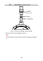
Gasket

Adapter

Torque 50 Nm

Sealing Ring


Figure 3-13


Secure the Adapter to Terminal Box 

5.


Connect wires to corresponding terminals. 

Note 

This terminal box transmits power without making any change to 
it.   

Summary of Contents for DS-2781 Series

Page 1: ...0 Explosion Proof Terminal Box Installation Guide UD08260B A 01000120180920 ...

Page 2: ...ntees or representations express or implied regarding to the Manual About this Manual This manual is applicable to Explosion Proof Terminal Box The Manual includes instructions for using and managing the product Pictures charts images and all other information hereinafter are for description and explanation only The information contained in the Manual is subject to change without notice due to fir...

Page 3: ...S BUSINESS INTERRUPTION OR LOSS OF DATA OR DOCUMENTATION IN CONNECTION WITH THE USE OF THIS PRODUCT EVEN IF HIKVISION HAS BEEN ADVISED OF THE POSSIBILITY OF SUCH DAMAGES REGARDING TO THE PRODUCT WITH INTERNET ACCESS THE USE OF PRODUCT SHALL BE WHOLLY AT YOUR OWN RISKS HIKVISION SHALL NOT TAKE ANY RESPONSIBILITES FOR ABNORMAL OPERATION PRIVACY LEAKAGE OR OTHER DAMAGES RESULTING FROM CYBER ATTACK HA...

Page 4: ...th Elastomeric Sealing Rings ATEX II 2 G D Ex db IIC T6 Gb Ex tb IIIC T80 Db IP68 IECEx Ex db IIC T6 Gb Ex tb IIIC T80 Db IP68 Hazardous Area Classification Zone 1 Zone 2 Zone 21 Zone 22 IP Degree IP68 2m 2h Ex Standards IEC 60079 0 2011 IEC 60079 1 2014 IEC 60079 31 2013 EN 60079 0 2012 EN 60079 1 2014 EN 60079 31 2014 Nameplate Explosion ProofTerminalBox WARNING DO NOT OPEN WHEN EXPLOSIVE ATMOSP...

Page 5: ...O EXIST Note For model difference see Section 1 2 WARNINGS 1 Ambient Temperature 40 C to 60 C for the terminal box and the cable gland with elastomeric sealing rings 2 When assembly operation and maintenance the operator must follow the requirements of the IEC 60079 14 latest version Explosive atmosphere Part 14 Electrical installation design Explosion ProofTerminalBox WARNING DO NOT OPEN WHEN EXP...

Page 6: ...e product correctly to avoid danger or property loss The precaution measure is divided into Warnings and Cautions Warnings Serious injury or death may occur if any of the warnings are neglected Cautions Injury or equipment damage may occur if any of the cautions are neglected Warnings Grounding The both internal and external earthing shall be connected reliably Warnings Follow these safeguards to ...

Page 7: ... environment with the anti electrostatic gloves When the device is installed on wall or ceiling it shall be firmly fixed Cautions Do not drop the device or subject it to physical shock To ensure explosion proof performance do not damage explosion proof surface Do not place the device in extremely hot cold the operating temperature shall be 40 C to 60 C or damp locations and do not expose it to hig...

Page 8: ...erences between operating environment and using history so regular checking is recommended for all the users Please contact with your dealer for more details If the product does not work properly please contact your dealer or the nearest service center Never attempt to disassemble the device yourself We shall not assume any responsibility for problems caused by unauthorized repair or maintenance ...

Page 9: ...allation Guide 8 Table of Contents 1 Introduction 9 1 1 Overview 9 1 2 Model Description 9 2 Appearance 11 3 Installation 13 3 1 DS 2781 and DS 2783 Series Installation 13 3 2 DS 2780 and DS 2782 Series Installation 19 ...

Page 10: ...odel Description This manual is applicable to the following models Table 1 1 Applicable Model and Feature Product Model Power Adapter Preinstalled Cable Gland Use DS 2781ZJ X DS 2781ZJ X 316L DS 2783ZJ X Yes Input 110 to 240 VAC Output 12 VDC Use cable gland sealed with setting compound buy separately DS 2780ZJ X DS 2780ZJ X 316L DS 2782ZJ X No Input Output 110 to 240 VAC Use cable gland with elas...

Page 11: ...Model Hawke ICG623 B M25 SS CMP N P Brass 25 PX2KX REX M25 Explanation of model naming DS 2 7 8 0 ZJ X 316L Hikvision product Front end product Material stainless steel Product type terminal box Product series Power adapter included 1 and 3 NO power adapter 0 and 2 Product type accessory Stainless Steel Type With 316L stainless steel 316L Without 316L stainless steel 304 Feature explosion proof Mo...

Page 12: ...Terminal Box Installation Guide 11 2 Appearance 272 272 96 8 Ø 182 4 Ø 8 5 EQS Figure 2 1 Explosion Proof Terminal Box Overview ...

Page 13: ...ide 12 1 2 Figure 2 2 Elastomeric Sealing Rings Overview Table 2 1 Accessory Description No Description 1 Elastomeric sealing rings DS 2780 and DS 2782 series included 2 M25 1 5 to G3 4 adapter DS 2780 and DS 2782 series included ...

Page 14: ... 240 VAC DS 2780 and DS 2782 series supports multiple power types Make sure the power meets anyone of 110 to 240 VAC 24 VAC 8 to 36 VDC PoE 802 3af and PoE 802 3at Make sure that the wall is strong enough to withstand four times the weight of the device Keep the device from bumps or scratches during installation 3 1 DS 2781 and DS 2783 Series Installation Before you start Cable gland sealed with s...

Page 15: ... screw holes Ø8 mm according to the dimension of the terminal box see Figure 2 1 and insert four M8 80 expansion bolts 2 Secure the terminal box on mounting place Nut Spring Washer Flat Washer Figure 3 1 Secure Terminal box 3 Disassemble the terminal box ...

Page 16: ...osite end and take out the gaskets and the sealing rings Note Normally two ends are enough for cable routing The others are reserved for unexpected conditions Keep the unused ends firmed sealed torque 50 Nm 2 Unscrew and remove the cover Note When removing the cover Do NOT release the safety rope Prevent the explosion suppression surfaces from bump or scratch ...

Page 17: ... Install the camera cable to cable gland sealed with setting compound Refer to installation guide of the cable gland for detailed steps 2 Secure the cable gland together with the cable gland sealing ring a component of cable gland to the Camera end Note For the torque information refer to the installation guide of the cable gland ...

Page 18: ...Ring Figure 3 4 Install Camera Cable 3 Connect wires to corresponding terminals 4 Install a RJ45 head to network cables and plug it to RJ45 5 Repeat above steps to route source cables through the opposite Camera end connect wires install a RJ45 head and plug it to RJ45 ...

Page 19: ...Terminal Box Installation Guide 18 To Camera To Source RJ45 RJ45 Figure 3 5 Wiring 5 Screw the cover back to terminal box ...

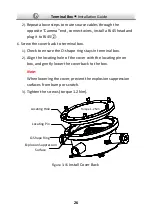
Page 20: ...event the explosion suppression surfaces from bump or scratch 3 Tighten the screws torque 1 2 Nm Locating Hole Locating Pin O Shape Ring Explosion Suppression Surface Torque 1 2 Nm Figure 3 6 Install Cover Back 3 2 DS 2780 and DS 2782 Series Installation Steps 1 Drill four screw holes Ø8 mm according to the dimension of the terminal box see Figure 2 1 and insert four M8 80 expansion bolts 2 Secure...

Page 21: ...minal Box Installation Guide 20 Nut Spring Washer Flat Washer Figure 3 7 Secure Terminal box 3 Disassemble the terminal box Cover Sealing Ring Gasket Plug Safety Rope Figure 3 8 Disassemble Terminal Box 1 ...

Page 22: ...nexpected conditions Keep the unused ends firmed sealed torque 50 Nm 2 Unscrew and remove the cover Note When removing the cover Do NOT release the safety rope Prevent the explosion suppression surfaces from bump or scratch Explosion Suppression Surface Figure 3 9 Disassemble Terminal Box 2 4 Route cables Cable routing with and without flexible conduit are different If camera is NOT protected by f...

Page 23: ...cording to the diameter of your cable Four kinds of sealing rings are supplied Ø12mm Ø9mm Ø7mm and Ø5mm 2 Secure the gland nut to the Camera end with wrench torque 50 Nm M25 to G Adapter Gasket Sealing Ring torque 50 Nm Figure 3 10 Install Camera Cable If camera is protected by flexible conduit follow these steps 1 Remove the thread cap on supplied adapter ...

Page 24: ...e conduit Conduit Sealing Ring of Conduit Adapter Camera Cable Figure 3 12 Install Adapter to Conduit 3 Thread the camera cable through the adapter gasket supplied sealing ring and the box outlet Note Select a suitable sealing ring according to the diameter of your cable Four kinds of sealing rings are supplied Ø12mm Ø9mm Ø7mm and Ø5mm 4 Secure the adapter to the Camera end with wrench torque 50 N...

Page 25: ...allation Guide 24 Gasket Adapter Torque 50 Nm Sealing Ring Figure 3 13 Secure the Adapter to Terminal Box 5 Connect wires to corresponding terminals Note This terminal box transmits power without making any change to it ...

Page 26: ...Terminal Box Installation Guide 25 To Camera RJ45 To Source RJ45 Figure 3 14 Wiring 1 Install a RJ45 head to network cables and plug it to RJ45 ...

Page 27: ...Check to ensure the O shape ring stays in terminal box 2 Align the locating hole of the cover with the locating pin on box and gently lower the cover back to the box Note When lowering the cover prevent the explosion suppression surfaces from bump or scratch 3 Tighten the screws torque 1 2 Nm Locating Hole Locating Pin O Shape Ring Explosion Suppression Surface Torque 1 2 Nm Figure 3 15 Install Co...

Page 28: ...27 ...

Reviews: