GigE Line Scan Camera
·
User Manual
26
Figure 7-12
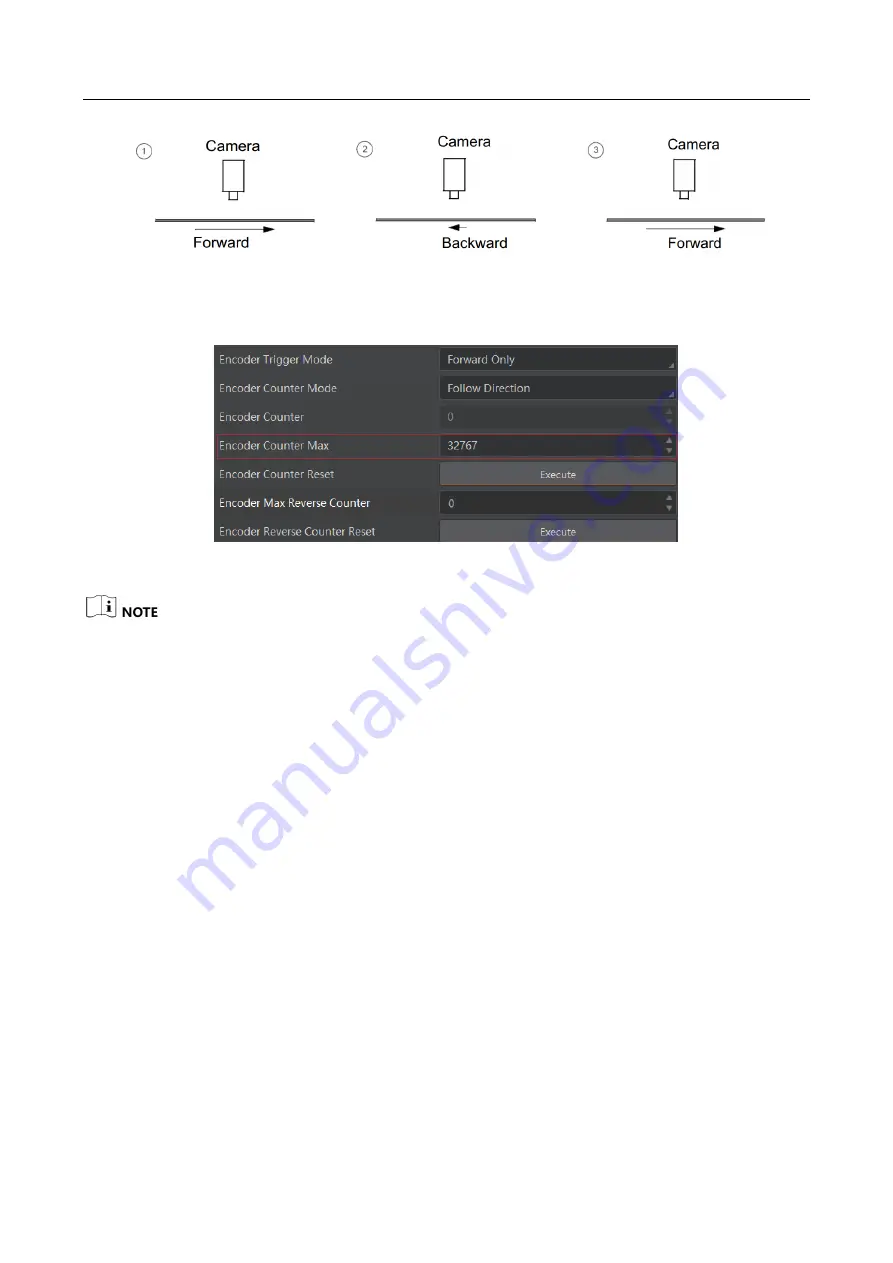
Counter Description
5.
(Optional) Set max. counter value (0 to 32767) in Encoder Counter Max.
Figure 7-13
Set Encoder Counter Max
After reaching the max. value, it will be cleared automatically or you can clear manually by clicking
Encoder Counter Reset.
6.
(Optional) Set Encoder Max Reverse Counter to avoid outputting images if the object moves
backward accidently during measurement, and click Execute in Encoder Reverse Counter
Reset to let the camera to output images again.
7.5.4 Set Frequency Converter Control
If the camera enables the frame trigger or the line trigger, you can select Frequency Converter as
trigger source. The hardware signal trigger or shaft encoder control signal can be converted into
the signal frequency of frame trigger or line trigger by camera’s frequency converter module.
The frequency converter module includes PreDivider, Multiplier and PostDivider. The signal after
being processed by these 3 modules is the camera’s final trigger signal.
PreDivider
The input signal first enters the PreDivider module, which reduces source signal frequency via
integer division, and then the signal is sent to the Multiplier module.
The PreDivider module reduces periodic jitter on the input signal, and signals above 100 kHz must
go through the PreDivider module to reduce the frequency for the Multiplier can only receive
signals in the range of 10 Hz to 100 kHz frequency range. The periodic jitter of shaft encoder signal
is accepted.
Summary of Contents for MV-CL021-40GM
Page 1: ...GigE Line Scan Camera User Manual ...
Page 126: ...UD24388B ...


