ENGINEERING YOUR SAFETY
WWW.HIGHWAYCARE.COM
Rev. C
–
10/18
©2018 Highway Care Limited. All Rights Reserved.
Page
1
of
61
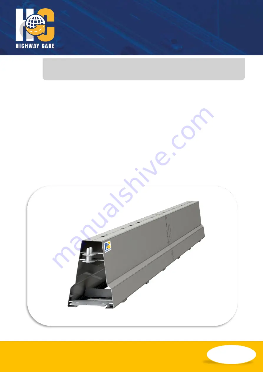
Product and Installation Manual
BG800
Australia & New Zealand
Temporary & Permanent Applications
Page 1: ...INEERING YOUR SAFETY WWW HIGHWAYCARE COM Rev C 10 18 2018 Highway Care Limited All Rights Reserved Page 1 of 61 Product and Installation Manual BG800 Australia New Zealand Temporary Permanent Applications ...
Page 2: ... 4 Testing Acceptance 4 Characteristics 4 Design Considerations 5 Median Roadside Applications 5 Length 5 Curves 5 Environment 5 Slopes 5 Length of Need 6 Ground Conditions 6 Crash Cushions 6 Anchoring 7 Delineators 7 Kerbs 7 Drainage 7 Weight 7 Safety Zone 8 Testing 8 System Types 9 Calculated Deflections 10 Standard NCHRP 350 TL 3 11 Standard NCHRP 350 TL 4 11 Standard MASH TL 3 12 Lower Deflect...
Page 3: ... Sided Intermediate Anchors 32 Different Anchor Types Installation 34 Barrier Removal 35 Noise Pollution 35 Other Operations 36 Curved Barrier 36 Offset Ends to Barrier 39 Anti Gawk Screen 40 Mesh Fence 40 Expansion Joints 41 T Top 42 Gate 43 Turning the Barrier Over 44 Inverting BG800 44 Righting Inverted BG800 44 Maintenance Repair 45 Galvanising Durability 45 Photo Examples 47 Frequently Asked ...
Page 4: ... are various connections to other barrier systems and crash cushions There is a standard system which is BG800 and two main system variations These are MDS Minimum deflection system and LDS Limited deflection system Testing Acceptance BG800 has been developed as a rapidly deployable Steel Safety Barrier for use where a vehicle restraint system conforming to both American European test standards wi...
Page 5: ... acceptance conditions which may differ to the above recommendations Curves Various degrees of movement can be achieved using the following components 0 67 at the QuickLink joint 5 at the 6m slotted plates joint 5 radius section 10 radius section Examples of achievable curves can be found in the Curved Barrier section of this manual Environment BG800 should not be installed where there are fixed o...
Page 6: ...etails of common ground conditions and the available types of anchors and anchor shoes can be found in drawing BG 60 23 and in the appendix of this manual Note For use of BG800 on any ground conditions or anchors that are not shown in this drawing please contact Highway Care Ltd for further advice Crash Cushions When choosing a suitable crash cushion for use with BG800 special consideration must b...
Page 7: ...e deflection of the system intermediate anchoring can be introduced to create the BG800 Minimum Deflection System MDS and Limited Deflection System LDS Delineators Reflective delineators can be attached to the side wall or top of the BG800 as required and at the relevant spacing s There are two options of delineators available one a fixed reflector and the second a reflector with a flexible joint ...
Page 8: ... TL 2 TL 3 or TL 4 MASH TL 3 and BS EN 1317 Containment Level T1 T2 T3 N1 N2 H1 or H2 The design features of the BG800 enable it to be deployed as either a single or double sided barrier However a factor to be taken into consideration when being utilised as a double sided barrier is the working width or deflection of the system The table below describes some of the test criteria met by BG800 Test ...
Page 9: ...ASH TL 3 100 1 66 NCHRP 350 TL 4 80 1 74 TL 3 100 1 60 TL 2 70 1 36 Anti Gawk System AGS 36 NCHRP 350 TL 2 10 km h 80 0 94 Lower Deflection System LDS 12 NCHRP 350 TL 4 80 0 42 TL 3 100 0 89 Minimum Deflection System MDS 6 NCHRP 350 TL 3 100 Top 0 305 Toe 0 076 MASH TL 3 100 Top 0 470 Toe 0 130 Notes MDS systems require the addition of T Top sections along the top of the barrier See T Top section ...
Page 10: ...mic deflection and working width shall be measured and recorded in the test report Normalised Dynamic Deflection DN m 2 2 M M M T T T M N Sin V M Sin V M D D Normalised Working Width WN m N M M N D D W W Where Measured Maximum Dynamic Deflection DM m Measured Working Width WM m Test Total Mass MT kg Test Velocity VT m s Test Angle θT Measured Test Total Mass MM kg Measured Test Velocity VM m s Mea...
Page 11: ...07 0 16 0 27 0 42 37 60 0 03 0 10 0 22 0 39 0 60 40 64 0 03 0 12 0 26 0 45 0 69 43 70 0 03 0 14 0 31 0 53 0 82 50 80 0 05 0 18 0 40 0 70 1 07 56 90 0 06 0 23 0 51 0 88 1 35 60 97 0 07 0 26 0 58 1 02 1 55 62 100 0 07 0 28 0 62 1 09 1 66 Standard NCHRP 350 TL 4 Below is a table showing the expected deflections of the TL 4 BG800 system if impacted at various angles and various speeds with an 8000kg T...
Page 12: ...0 11 0 22 0 44 0 67 43 70 0 03 0 13 0 25 0 52 0 79 50 80 0 04 0 17 0 30 0 68 1 03 56 90 0 06 0 22 0 39 0 86 1 31 60 97 0 06 0 25 0 49 0 99 1 51 62 100 0 07 0 27 0 56 1 06 1 61 Lower Deflection System LDS NCHRP 350 TL 3 Below is a table showing the expected deflections of the LDS TL 3 BG800 system if impacted at various angles and various speeds with a 2000kg Truck 12 0m Between Anchors Impact Spee...
Page 13: ...00 0 01 0 02 0 03 0 05 31 50 0 00 0 01 0 03 0 05 0 07 37 60 0 00 0 02 0 04 0 07 0 11 40 64 0 01 0 02 0 05 0 08 0 12 43 70 0 01 0 02 0 05 0 09 0 14 50 80 0 01 0 03 0 07 0 12 0 19 56 90 0 01 0 04 0 09 0 16 0 24 60 97 0 01 0 05 0 10 0 18 0 27 62 100 0 01 0 05 0 11 0 19 0 29 Impact Speed mph Impact Speed km h Deflection at Toe m 5 10 15 20 25 25 40 0 00 0 00 0 00 0 01 0 01 31 50 0 00 0 00 0 01 0 01 0 ...
Page 14: ...0 01 0 03 0 05 0 07 31 50 0 00 0 02 0 04 0 08 0 11 37 60 0 01 0 03 0 06 0 11 0 17 40 64 0 01 0 03 0 07 0 12 0 19 43 70 0 01 0 04 0 08 0 15 0 22 50 80 0 01 0 05 0 11 0 19 0 29 56 90 0 02 0 06 0 14 0 24 0 37 60 97 0 02 0 07 0 16 0 28 0 43 62 100 0 02 0 08 0 17 0 30 0 46 Impact Speed mph Impact Speed km h Deflection at Toe m 5 10 15 20 25 25 40 0 00 0 00 0 01 0 01 0 02 31 50 0 00 0 01 0 01 0 02 0 03 ...
Page 15: ...plates at join 6m wheelset male female QuickLink 5 degree 10 degree angle sections left right Crash cushion end treatment 6m gate section 1 4m gate post 3m gate hinge Notes All M16 bolts used for connecting sections of BG800 together to be at least grade 8 8 Numerous extra components are available and bespoke options also Please contact Highway Care for further information Future Highway Care manu...
Page 16: ...hortening clutch These chains are for lifting 6m lengths of barrier that are half of the 12m sections Tag Rope Rope with spring loaded carabineer clip The rope length needs to be 1 5 times the lifting height of the barrier Drilling Equipment Either an electric hammer drill c w 32mm drill bit or an air driven rock drill c w 33mm rock drill tool To speed up installation consideration should be given...
Page 17: ...mm x 75mm timber bearers Small Impact Gun Complete with suitable sockets 24mm impact socket as a minimum Compressor Extension Pipes For the Rock Drills and Impact Gun Should be capable of driving two rock drills at once Spanners Wrenches Combination spanners to include as a minimum 2 of each of the following 13mm 24mm 30mm 32mm 36mm Drive Socket Sets Torque Wrench S Suitable for torques up to 150 ...
Page 18: ...fied In the case of concrete pavements if reinforcement is encountered when drilling that this can be drilled through The method of reinstatement of drilled holes when the BG800 is removed There are no underground services waterproof membranes etc Which could be damaged by drilling There are no overhead cables that could be contacted by the lifting operation There is adequate working room and safe...
Page 19: ...ts along its length BG800 has identical lifting points on the underside to facilitate lifting inverted sections If the barrier to be lifted has a bolted joint in its length I E A section made from two pieces then using the standard chains the barrier must be lifted from the lifting points closest to and either side of this bolted joint If the length of barrier is a piece without a joint in the mid...
Page 20: ...be checked before use to ensure That they are undamaged The load imposed is within their capacity The recommended chains to use are two leg sets each leg 2 metres long each with a shortening clutch to allow tilting the barrier if required They are rated at 2 tons per pair provided that the angle between the legs does not exceed 90 or 2 tons per leg if one leg is used with the chain vertical It is ...
Page 21: ...t the terminal end Shorten one chain by about six links to get a more even centre of gravity Barrier where the central joint has been angled to follow a curve will not lift level with a two leg chain Where the angle is more than 1 2 it is advisable to use 2 two leg chains on the crane hook One two leg chain will need to have 3 metre legs both with shortening clutches The other two leg chains will ...
Page 22: ...at may be required When loading trailers with chains it will be necessary for somebody to be on the top of the load to position the barrier and detach the lifting chains from the barrier This is a potentially dangerous operation and great care must be taken The following precautions must be observed When climbing onto the load a ladder must be used This must extend at least 1 metre above the load ...
Page 23: ...ut 2 metres from the ends of the barrier and clear of the feet of the inverted first layer units and the feet of the second layer units Secure the second layer with two 2000kg ratchet straps Place the third layer on similar timbers and secure with ratchet straps When placing ratchet straps over the layers ensure that the two on the bottom layer are nearer the centre and space the straps for the su...
Page 24: ...he first layer units and the feet of the second layer units Secure the second layer with two 2000kg ratchet straps Place the third layer on similar timbers and secure with ratchet straps When placing ratchet straps over the layers ensure that the two on the bottom layer are nearer the centre and space the straps for the subsequent layers further out towards the ends On each layer not secured by a ...
Page 25: ...m The safe working load of the equipment That there are no defects with the equipment That there are no overhead cables That the vehicle is stabilised That the vehicle is on reasonably level ground Before lifting the load it is recommended the operator should Check the safe working load of any slings or chains Establish the weight of the load Check that the area to receive the load is clear Ensure...
Page 26: ...ENGINEERING YOUR SAFETY WWW HIGHWAYCARE COM Rev C 10 18 2018 Highway Care Limited All Rights Reserved Page 26 of 61 ...
Page 27: ...n is normally started from the end of the BG800 and laid in the direction of traffic flow Sometimes when a long length of BG800 is to be installed and site conditions allow the installation can commence at any point along the length of the run using a section of BG800 with two male ends as the first unit to be placed and subsequent standard sections laid outwards in both directions from this secti...
Page 28: ... as agreed with the client prior to installation see Drilling for Anchors section 4 Remove the 8 bolts 3 along each side and 2 on the end from the end cap hood section of the barrier and lift off the terminal cover approx 30kgs 5 Drill through the anchor plate and fasten using the appropriate method as agreed with the client prior to installation see Drilling for Anchors section Replace and secure...
Page 29: ...chors section For the departure end the procedure is similar to that of the approach end Once the securing of the QuickLink has been completed then either fix the external anchor to the ground or lock the terminal to the inner anchor shoe and then fix the end of the terminal as detailed in the Terminal Installation section Laying BG800 The barrier should be unloaded from the truck as detailed in t...
Page 30: ...sit flush unhook the leg of the chain nearest the joint being made bring the other chain leg vertical and lift and lower on this leg The last option is to lift the last installed section of BG800 place a timber bearer under the male end and lower the BG800 onto this timber bearer Then lower the next section of BG800 into place and connect Once the connection is made and the joint flush within 10mm...
Page 31: ...washers must be located inside the barrier The bolts should be tightened to a torque ranging between 100 and 200 Nm i e normal spanner tight To fit an intermediate anchor at the bolted joint the BG800 must be inverted see Lifting section and Inverting section Once inverted safely the 2 small barrier joint plates need to be removed and swapped with the intermediate anchor small lower joint plates u...
Page 32: ... options Drilling for Anchors Hole Sizes Holes for securing BG800 are drilled 32mm diameter for the asphalt pins 30mm for mechanical anchor bolts and 28mm diameter for resin anchors Note Always follow the installation instructions supplied by the fixing manufacturer Using Hammer Drill A commonly used drill is a Hilti TE 76 ATC The ATC in its name refers to the system which stops the drill spinning...
Page 33: ...ough Use tape on the drill bit or a depth stop Do not drill deeper than necessary If reinforcing bar is found in the concrete stop using the hammer drill and drill through the bar with a diamond core drill Using a Wet Diamond Core Drill The diamond core drill is generally used just to cut through reinforcing bar found when hammer drilling concrete The system used consists of a drill incorporating ...
Page 34: ...to the ground using a large hammer sledge hammer as required Note Flag top pins should not be used on any external anchor Pins are normally used on temporary installations only Mechanical Anchor Bolt FMA 24 185 YZ 1 Drill a hole with a diameter of 30mm and a depth of 250mm 2 Clean out the hole using an air line and blow pipe or similar 3 Insert the complete mechanical anchor into the hole 4 Tighte...
Page 35: ...esin anchors unscrew easily Cut off the remaining studding Asphalt pins can normally be loosened by tapping sideways with a hammer and pulled out of the hole A large crow bar could be used to aid removal If pins are tight in the terminal end and or inner anchor shoe they could be attached to the crane using a ring and shackle Apply a small amount of lift and rotate the pin by using a large adjusta...
Page 36: ... 5 or 10 angle and are quickly installed using the standard QuickLink connections 4 Replacing the standard joining plates at the bolted joint in the barrier with slotted plates designed to allow up to a 5 bend in the barrier Where these plates are fitted the bolts need to be slackened slightly to set required angle and then all bolts at the joint where the plates are installed must be re tightened...
Page 37: ...gle Radius Metres Offset Metres at end of 12m Type 1 Movement on QuickLink 0 67 1030 0 14 1 2 Slackening standard bolted joint 1 5 460 0 15 2 3 2 degree radius piece 2 5 275 0 52 1 3 5 degree radius piece 5 137 1 00 1 4 5 degree bend using slotted plates 5 137 0 50 2 3 4 5 radius piece 5 slotted plates 10 69 1 56 3 3 4 As above but 3m 3m 6m overall 10 35 1 56 3 ...
Page 38: ...ENGINEERING YOUR SAFETY WWW HIGHWAYCARE COM Rev C 10 18 2018 Highway Care Limited All Rights Reserved Page 38 of 61 Achievable Radius Flexibility Roundabout Component Layout Example ...
Page 39: ...ed either by utilising the movement in the QuickLinks to curve the BG800 layout to create a flare away from the traffic lane or a BG800 5 radius piece can be placed in the barrier run at the correct joint to create a flare Use of 5 radius section offset end of barrier run QuickLink offset taper end of barrier run Connections There are the following connections available for BG800 to other barrier ...
Page 40: ...800 contractors must ensure the anchor spacing and type of anchors are adequate to allow for the wind loading requirements Refer to drawing BG 70 38 for further detail Note Please Contact Highway Care for further information Mesh Fence A security fence is available for non highway roads applications This can be used to give added security to private sites to deter unauthorised access Note Please C...
Page 41: ...uld be pre installed and correctly located and identified on the load for speed of installation If this is not possible however this process can be performed on site For sites where the expansion of the ground that the BG800 is to be anchored to is a concern there is a special section of BG800 called a Variable Length Section which could be utilised This requires T Top sections on the adjacent bar...
Page 42: ... aligned with one 6m half section of barrier and then locked down using two bolts per 6m length secured into special nut attached to them The special nut is passed through the relevant slot in the top of the barrier and then turned 90 to lock it into the slot to allow the bolt to be tightened down to secure the T top One section of T top is then attached to the next by use of two splice plates eit...
Page 43: ...r installation using the QuickLinks can then resume from this departure end fixed gate post At each end of the BG800 Gate an external anchor shoe will be attached to the fixed gate post and will require anchoring see External Anchor Shoe section In addition at the QuickLink joints immediately before and after the gate an intermediate anchor will be required see Intermediate Anchoring section Note ...
Page 44: ... at the bottom of this page 1 Lower the barrier onto a wooden block 2 The centre of the barrier settles on the block clear of cross members and with only one side of the barrier supported by the block 3 Continue lowering the barrier until it lies on its side Transfer the chains from the lifting eyes on the top of the barrier to the lifting eyes on the bottom of the barrier 4 Start to lift the inve...
Page 45: ...hows the indicative corrosion rates for various environments We can estimate the expected lifespan of BG800 components This estimated lifespan is from 20 100 years and based on the assumption that the zinc coating on any of the components remains undamaged If damage to the zinc coating is carefully controlled it is reasonable to accept that the lifespan will be extended Repair Usually after a desi...
Page 46: ...damaged sections by placing a piece of coloured insulation tape or coloured cable tie around the outer pin of the male QuickLink between the two plates that hold the pin If possible cable tie on a label with the description of the damage where and when it occurred If during loading or installation of the BG800 the installer finds a damaged section they are unsure of using do not use it until it ha...
Page 47: ...SAFETY WWW HIGHWAYCARE COM Rev C 10 18 2018 Highway Care Limited All Rights Reserved Page 47 of 61 Photo Examples Standard Install LDS Install MDS Install Bridge Install T Top Transition Section Variable Length Barrier ...
Page 48: ... YOUR SAFETY WWW HIGHWAYCARE COM Rev C 10 18 2018 Highway Care Limited All Rights Reserved Page 48 of 61 Barrier Trailer Lifting Grab Lifting Cradle Full height End Section External Anchor Shoe Intermediate Anchor ...
Page 49: ...R SAFETY WWW HIGHWAYCARE COM Rev C 10 18 2018 Highway Care Limited All Rights Reserved Page 49 of 61 Security Nut Installation Gate Post Hinge Joint Joining BG800 Anti Gawk Screen Security Fence Typical Impact Damage ...
Page 50: ...equired with the frequency dependent on the system used Standard every 60m MDS every 6m LDS every 12m 5 On average how long does it take to install BG800 Depending on the application and circumstances at the site experience of the workforce equipment available pre assemble taken place once the ground conditions are suitable installation of a trailer with fifteen 12m standard sections can be comple...
Page 51: ...BG800 Minimum Deflections System MDS might be the best option for this application With the additional T top sections and anchors every 6m deflection is minimal refer to crash test deflection results and it may be appropriate to risk assess the deflection figure using the calculated deflection tables in this manual 12 I want to install BG800 on a bridge deck is this possible BG800 can be installed...
Page 52: ... M24 460mm threaded bar with resin 1 Kelkin Leftie 18 25 464mm with Keligrout 1 Kelkin Leftie 14 25 362mm with Keligrout M24 Mechanical Anchor M24 460mm threaded bar with resin 1 Kelkin Leftie 18 25 464mm with Keligrout M24 460mm threaded bar with resin Not permitted see note Not permitted see note Not permitted see note MDS 6 metre anchoring M24 250mm threaded bar with resin M24 460mm threaded ba...
Page 53: ...with Highway Care Screen 12 metre anchoring M24 250mm threaded bar with resin M24 460mm threaded bar with resin 1 Kelkin Leftie 18 25 464mm with Keligrout 1 Kelkin Leftie 14 25 362mm with Keligrout M24 Mechanical Anchor M24 460mm threaded bar with resin 1 Kelkin Leftie 18 25 464mm with Keligrout M24 460mm threaded bar with resin Not permitted see note Not permitted see note Not permitted see note ...
Page 54: ...or banksman Operative to be vigilant Instruction Training Training Injury to hands Use of PPE gloves Use of correct tools Competent crane operator banksman Operative to be vigilant Instruction Training Training Training Injury to feet Use of PPE safety boots Competent crane operator banksman Operative to be vigilant Instruction Training Training Load slipping from crane Use certified approved slin...
Page 55: ...g delivery vehicle Competent banksman Competent driver Operatives to be vigilant Training Training Training Injury from traffic Correct traffic management procedures Operatives to be vigilant Training Training Electrocution from or damage to overhead power lines or cables Site inspection prior to installation Training Hazard Precautions to minimise the risk Actions Injury to head Use of PPE hard h...
Page 56: ... dusk mask Training Injury to skin from chemical anchor resin Use of PPE gloves Training Injury from traffic Correct traffic management procedures followed and operatives to be vigilant Training Hazard Precautions to minimise the risk Actions Load slipping Use certified slings Use competent slinger Inspection Training Injury to heads Use of PPE hard hat Instruction Injury to feet Use of PPE steel ...
Page 57: ...o Are the anchors selected suitable for the pavement condition Yes N A No Are all the components available Yes N A No Do the anchor shoes have the lynch pin installed Yes N A No Are the start and end sections installed correctly with all 8 anchors installed Yes N A No Are all the QuickLink security nuts installed Yes N A No Has any intermediate anchoring been used If so note the spacing here______...
Page 58: ...ENGINEERING YOUR SAFETY WWW HIGHWAYCARE COM Rev C 10 18 2018 Highway Care Limited All Rights Reserved Page 58 of 61 Other Information Comments Reference Drawing Please note any variations ...
Page 59: ...conditions apply ABSORB 350 Crash Cushion is not to be used as this is for temporary use only Flat Flag top pins are not to be used as these are for temporary use only M24 threaded bar with resin is recommended for anchoring After initial installation it is recommended that the site is revisited after 1 month for inspection After this it is recommended a thorough inspection is carried out every 5 ...
Page 60: ...frastructure http www dpti sa gov au standards raod_safety_ barriers Victoria Vic Roads https www vicroads vic gov au business and industry technical publications technical publications a to z Queensland Department of Transport and Main Roads https www tmr qld gov au business industry Business with us Approved products and suppliers Traffic engineering and road safety approved products aspx Wester...
Page 61: ...GINEERING YOUR SAFETY WWW HIGHWAYCARE COM Rev C 10 18 2018 Highway Care Limited All Rights Reserved Page 61 of 61 Contact Details Visit www highwaycare com Email info highwaycare com Call 44 0 1622 734215 ...