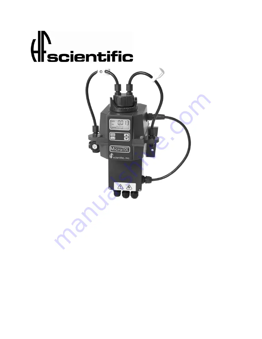
OWNER’S MANUAL
MicroTOL Series Turbidimeter
HF scientific
3170
Metro
Parkway
Ft. Myers, FL 33916
Phone:
239-337-2116
Fax:
239-332-7643
Catalog No. 24034 (8/07)
E-Mail:
[email protected]
Rev. 4.1
Website: www.hfscientific.com
Page 1: ...MANUAL MicroTOL Series Turbidimeter HF scientific 3170 Metro Parkway Ft Myers FL 33916 Phone 239 337 2116 Fax 239 332 7643 Catalog No 24034 8 07 E Mail hfinfo watts com Rev 4 1 Website www hfscientif...
Page 2: ......
Page 3: ...ions Immunity Tested and passed EN61326 1997 A1 1998 A2 2001 A3 2003 Manufacturer s Name HF scientific Manufacturer s Address 3170 Metro Parkway Fort Myers Florida 33916 7597 Importer s Name Importer...
Page 4: ......
Page 5: ...cal Connections 7 3 3 1 Power 8 3 3 2 RS 485 8 3 3 3 Relays 8 3 3 4 4 20 mA 8 4 0 Operation 9 4 1 Routine Measurement 9 4 2 Security Access Feature 9 5 0 Instrument Calibration 11 5 1 Calibration Stan...
Page 6: ...8 1 Backlit LCD 24 8 2 Ultrasonic Cleaning 24 8 3 RS 485 Output 25 8 3 1 HF Online 25 8 3 2 Simple Communication 25 8 3 3 Modbus Communication 26 8 4 Flow Alarm 26 8 5 Flow Controller 26 8 6 Remote Pa...
Page 7: ...0 ml min 1 liter min 026 26 Gal min Operating Temperature 1 C 50 C 34 F 122 F Wetted Materials Nylon Borosilicate Glass Silicon Polypropylene Stainless Steel Sample Temperature Range 1 C 50 C 34 F 122...
Page 8: ...ard on all Micro TOL instruments and will reduce pressures up to 1380kPa 200 PSI down to 104kPa 15 PSI 1 1 The Micro TOL Series The Micro TOL series instruments have a wide variety of options availabl...
Page 9: ...please immediately contact the local distributor or the HF scientific inc Customer Service department Note The spare cuvette part 50033 is not included for models 20055 20056 20063 20064 1 3 The Displ...
Page 10: ...r line in the event that the desiccant pouch needs replacement Replacement desiccant pouches are available from HF scientific inc or the local representative Part 21555R Refer to section 10 2 Replacin...
Page 11: ...n and service and ensure that the front display rests at eye level The overall mounting dimensions of the instrument are shown in Figure 3 The recommended mounting screws are M6 for the instrument enc...
Page 12: ...I The maximum allowable fluid temperature is 50 C 122 F Figure 4 Recommended Plumbing for the Instrument The instrument is equipped to be plumbed using 4 75 mm 3 16 ID 8 mm 5 16 OD flexible tubing Opa...
Page 13: ...erminal box which should be located directly under the sensor portion of the instrument The connections are labeled within the terminal box and are self descriptive see Figure 5 Please follow all loca...
Page 14: ...led beneath this termination 3 3 3 Relays The Alarm 1 and Alarm 2 relays are mechanical relays rated at 240 VAC 2A Please note that the relays are labeled NO Normally Open NC Normally Closed and C Com...
Page 15: ...ing on the upper row of the display see illustration below 4 1 Routine Measurement The following steps describe how to measure the turbidity of a sample using this instrument 1 Apply power to the inst...
Page 16: ...nd then press the button to accept the first number of the code Now enter the second number in the code Proceed as with the first number followed by Then repeat the process for the third number in the...
Page 17: ...rocedures step 5 We recommend that the following materials be used during calibration to achieve the full scale accuracy stated in this manual 1 0 02 NTU Calibration Standard available from HF scienti...
Page 18: ...000 NTU standard Index the standard to the lowest value on the upper display 4 Press the button to accept the calibration 5 The lower display will count down the progress of the calibration step 6 The...
Page 19: ...the measurement chamber be kept covered during the calibration period and that the flow through cuvette be replaced immediately after the calibration to prevent premature saturation of the desiccant 5...
Page 20: ...ts turbidity using a laboratory turbidimeter contact the HF scientific inc customer services department for examples of laboratory turbidimeters 3 Compare the turbidity reported by the instrument to t...
Page 21: ...dity and locate the position of the cuvette having the lowest reading 3 With the calibration standard positioned at the location having the lowest turbidity reading install the Indexing Ring over the...
Page 22: ...il the arrow beside CONFIG is illuminated then press the button Note To exit the CONFIG mode press the MODE EXIT button 7 1 Selecting the Output O P The first configuration selection is the O P The se...
Page 23: ...ipped with this option and the I O selection is changed to 485 prompts will appear for setting the baud rate and the address Select the correct baud rate 1200 2400 4800 9600 or 19200 for operation of...
Page 24: ...NTU Alarm Delay Time The alarm delay times are used to prevent ringing of the alarm when the measured turbidity level is close to the set point The function of the delay times is as follows Delay On...
Page 25: ...ired delay time has been set press the button to accept it Delay Off Next the following display will appear to select the number of seconds currently set for the delay off time The current selected nu...
Page 26: ...ngs are grouped together to prevent them from being adjusted by accident To gain access to the extended settings select On using the t or u buttons and press the button 7 8 Speed of Response The speed...
Page 27: ...to hide these digits Change the resolution by pressing the t or u button When the desired digit resolution has been selected press the button 7 10 LCD Backlight Brightness The LCD backlight brightness...
Page 28: ...0055 20056 20063 20064 This allows for a selection menu to turn off the ultrasonic cleaning function if desired The default mode is On Make a selection using the t and u buttons then press the button...
Page 29: ...en press the button to move to return to AUTO mode 7 15 Saving Configuration Settings If extended settings are set to OFF pressing the button will save all settings and the Micro TOL will automaticall...
Page 30: ...A will be sent to 2 mA If the correct cuvette is installed and the error is still posted try rotating the flow through unit slightly to improve the connection If this fails to work the cuvette may hav...
Page 31: ...system with an optional PC software package called HF ONLINE This system allows for an interface with up to 255 Micro TOL s for the purpose of data logging This system will interface directly with com...
Page 32: ...r website at www hfscientific com 8 4 Flow Alarm Catalog 19945A The flow switch for the Micro TOL is a factory installed option This option indicates a Low Flow condition by switching both relays to t...
Page 33: ...tions occurs both alarm relays will be activated and the 4 20 mA output will be held at 2 mA If any of these errors occur the instrument will still display readings however the accuracy is not known a...
Page 34: ...sure See section 3 2 and figure 4 3 For sever cases of bubbles a stilling chamber is available Call HF scientific Part 20106 Check flow through cuvette for condensate or leaks Clean cuvette See sectio...
Page 35: ...to time It is essential that the enclosure seal on the instrument base be maintained to ensure adequate desiccant life Inspect the seal each time the desiccant pouch is replaced Replace or reseat the...
Page 36: ...ck Solution 4000 NTU 500 ml 70914 Replacement Desiccant Pouch 21555R Software for data collection and reporting 19783 Flow Regulator Micro TOL 19778 Pressure Regulator 24306S Replacement Cuvette with...
Page 37: ...or defects resulting from repairs alterations or installation made by any person or company not authorized by HF scientific inc HF scientific inc assumes no liability for consequential damage of any k...
Page 38: ......
Page 39: ......
Page 40: ......
Page 41: ......
Page 42: ......