Preparing the
Preparing the server
server for installation
for installation
Procedure
Procedure
1. Observe the following warnings:
WARNING:
WARNING: The front panel Power On/Standby button does not shut off system power.
Portions of the power supply and some internal circuitry remain active until AC power is
removed.
To reduce the risk of personal injury, electric shock, or damage to the equipment, remove
power from the server:
For rack and tower servers, remove the power cord.
For server blades and compute modules, remove the server blade or compute module
from the enclosure .
WARNING:
WARNING: To reduce the risk of personal injury from hot surfaces, allow the drives and the
internal system components to cool before touching them.
2. Update the system ROM.
Locate and download the latest ROM version from the Hewlett Packard Enterprise Support Center website
Hewlett Packard Enterprise Support Center website . Follow the instructions
on the website to update the system ROM.
3. Power down the server (Power down the server).
4. Remove all power:
a. Disconnect each power cord from the power source.
b. Disconnect each power cord from the server.
5. Do one of the following:
Extend the server from the rack .
Remove the server from the rack .
6. Place the server on a flat, level work surface.
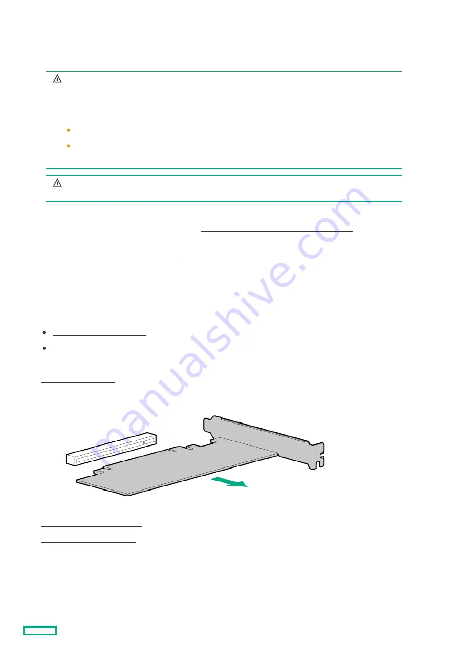
8. If needed, remove any expansion boards installed in slot 3.
9. Remove the primary PCI riser cage.
10. Install the TPM board and cover .
Preparing the server for installation
165
Summary of Contents for ProLiant DL360 Gen10 Plus
Page 8: ...Component identification Component identification 8...
Page 29: ...HPE Basic Drive LED definitions 29...
Page 31: ...BIOS Platform Configuration RBSU Hot plug fans 31...
Page 36: ...Operations Operations 36...
Page 47: ...Remove the secondary PCI riser cage 47...
Page 54: ...Accessing the Systems Insight Display 54...
Page 55: ...Setup Setup 55...
Page 73: ...Hardware options installation Hardware options installation 73...
Page 108: ...Installing an 8SFF optical drive 108...
Page 122: ...Secondary PCI riser options Secondary PCI riser options 122...
Page 129: ...Full length Installing an expansion board in the secondary riser cage 129...
Page 135: ...Installing a type a Smart Array storage controller option 135...
Page 140: ...Processor and heatsink options Processor and heatsink options 140...
Page 149: ...4 LFF 11 Connect the cable Installing the Systems Insight Display power module 149...
Page 160: ...HPE Trusted Platform Module 2 0 Gen10 option HPE Trusted Platform Module 2 0 Gen10 option 160...
Page 164: ...Installing the Trusted Platform Module board Installing the Trusted Platform Module board 164...
Page 167: ...4 Proceed to Preparing the server for operation Installing the TPM board and cover 167...
Page 173: ...Cabling Cabling 173...
Page 177: ...Front power SID USB cabling Front I O cabling 177...
Page 178: ...Storage cabling Storage cabling 178...
Page 181: ...8SFF x4 2SFF backplanes to type p controller 8SFF x4 2SFF backplanes to type p controller 181...
Page 183: ...2SFF x4 backplane to primary NVMe riser 2SFF x4 backplane to primary NVMe riser 183...
Page 187: ...8SFF x4 backplane direct attach 8SFF x4 backplane direct attach 187...
Page 188: ...8SFF SAS SATA backplane to embedded SATA 8SFF SAS SATA backplane to embedded SATA 188...
Page 191: ...4LFF backplane to controllers 191...
Page 192: ...Software and configuration utilities Software and configuration utilities 192...
Page 221: ...Keeping the system current Keeping the system current 221...
Page 234: ...Troubleshooting Troubleshooting 234...
Page 238: ...Removing and replacing the system battery 238...
Page 251: ...Support and other resources Support and other resources 251...


