background image

Operation

21

3

3..7

7 O

OIIL

L G

GU

UA

AR

RD

DIIA

AN

N™

™ ((A

Au

utto

o T

To

op

p--O

Offff))

During normal operation, the control automatically monitors vat oil level. If the control
senses oil level is too low, unit automatically pumps oil from BIB into vat to keep oil at
proper level.

3

3..7

7..1

1 M

Ma

an

nu

ua

all T

To

op

p--O

Offff

If oil level is a little low, oil can be added to vat at any time from BIB to raise oil level to
proper level by following steps below. This procedure is not to be used to fill an empty
vat.

1

1))

Press and hold the filter button (either one for full vat) until display shows
“*FILTER MENU*” followed by “1.EXPRESS FILTER”.

2

2))

Press the right arrow 5 times until “6.FILL FROM BIB” shows in display.

3

3))

Press “✓”; “FILL VAT” “✓=PUMP” “X=EXIT” is displayed.

4

4))

Press and hold “✓”; display shows “FILLING” and oil is pumped from the BIB to
the vat.

5

5))

Once vat is full, release “✓”; “FILL VAT” “✓=PUMP” “X=EXIT” displays. Press
“X” button twice for normal operation.

3

3..8

8 S

Se

elle

eccttiin

ng

g A

A P

Prro

od

du

ucctt W

Wiitth

h A

A D

Diiffffe

erre

en

ntt S

Se

ett--P

Po

oiin

ntt

When selecting a product, if “XXX XXX” shows in the display, the set-point
temperature is not correct for this product. To change the set-point temperature for the
desired product:

1

1))

Press product button, for ex: product 1 (FRY).

2

2))

Display shows “XXX XXX”.

3

3))

Press and hold timer 1 or 2 for 5 seconds and then “FRY” shows in display.

4

4))

Allow oil temperature to reach set-point temperature before dropping product.

1

1))

Control displays “BIB IS LOW” and an alarm sounds.

2

2))

Open right door, pull BIB from unit. Pull cap from BIB top, discard empty BIB,
and replace with full one.

3.9a Replacing the BIB

Summary of Contents for Wendy's Evolution Elite EEG-251

Page 1: ...97F OPERATOR S MANUAL EEG 251 EEG 252 EEG 253 EEG 254 W We en nd dy y s s E Ev vo ollu ut tiio on n E Elliit te e G Ga as s R Re ed du uc ce ed d O Oiill C Ca ap pa ac ciit ty y O Op pe en n F Fr ry y...

Page 2: ......

Page 3: ...2 Set Up Mode 16 3 3 Filling Or Adding Oil 18 3 3 1 Filling Vat From Bulk Supply 19 3 4 Morning Start Up Procedures 19 3 5 Basic Operation 20 3 6 Idle Mode 20 3 7 OIL GUARDIAN Auto Top Off 21 3 7 1 Ma...

Page 4: ...enance 46 3 20 Clean Blower Vents 46 Chapter 4 Information Mode 49 4 1 1 E Log Error Code Log 49 4 2 2 Last Load 50 4 3 3 Daily Stats 50 4 4 4 Oil Stats 51 4 5 5 Review Usage 52 4 6 16 USB Support 53...

Page 5: ...Contents iii...

Page 6: ...tative Maintenance Schedule 46 Table 6 1 Special Program Modes 59 Table 6 2 Special Programming Procedures 61 Table 7 1 Troubleshooting 69 Table 7 2 Error Codes 70 List of Figures Figure 2 1 Flexible...

Page 7: ...ce or is safety related the words DANGER WARNING CAUTION or NOTICE are used Their usage is described as follows D DA AN NG GE ER R indicates hazardous situation which if not avoided will result in dea...

Page 8: ...akeries hospitals etc but not for the continuous mass production of food such as in a factory setting During use the units airborne A weighted emission sound pressure is below 70 db A All repairs must...

Page 9: ...or steam cleaning tool Cleaning brushes are shipped with the appliance and proper cleaning instructions are included in this manual Proper maintenance also increases the usable life of the appliance...

Page 10: ...ions fully before installing or using the appliance For gas appliance installations in South Africa the installation shall be carried out by a registered installer and the installation shall comply wi...

Page 11: ...id Propane I3P 19 8 KW 67 560 Btu h Natural I2H 21 98 KW 75 000 Btu h 79 13 MJ h Natural I2E 21 98 KW 75 000 Btu h Natural I2E 21 98 KW 75 000 Btu h Natural I2L 21 98 KW 75 000 Btu h Natural I2HS 21 9...

Page 12: ...Preface x Injector Size Natural I2H 2 08 mm Natural I2E 2 08 mm Natural I2E 1 70 mm Natural I2L 2 30 mm Natural I2HS 2 30 mm Liquid Propane I3P 1 30 mm...

Page 13: ...ion Automatic oil top off Self diagnostic system built into controls Built in filter with automatic filtration Propane or natural gas 75 000 BTU vat 21 97 KW 1 1 3 3 P Pr ro op pe er r C Ca ar re e As...

Page 14: ...Introduction 2...

Page 15: ...ar re e w wh he en n m mo ov viin ng g t th he e f fr ry ye er r t to o p pr re ev ve en nt t p pe er rs so on na all iin njju ur ry y T Th he e f fr ry ye er r w we eiig gh hs s a ap pp pr ro ox xiim...

Page 16: ...or servicing and proper operation Choose a location which will provide easy loading and unloading without interfering with the final assembly of food orders Operators have found that frying from raw t...

Page 17: ...t tiio on n C Co od de es s G Ga as s B Bu ur rn niin ng g A Ap pp plliia an nc ce es s a an nd d llo oc ca all c co od de es s I In n A Au us st tr ra alliia a iin n a ac cc co or rd da an nc ce e w...

Page 18: ...talled It must also be installed with restraining means to guard against transmission of strain to the connector as specified in the appliance manufacturer s instructions 3 3 See Figure 2 1 Flexible G...

Page 19: ...Installation 7 Figure 2 1 Flexible Gas Line Cable Restraint Installation...

Page 20: ...e ec ct tiio on n iin n a allll u un ng gr ro ou un nd de ed d u un ne ea ar rt th he ed d c co on nd du uc ct to or rs s T Th he e m ma aiin n p po ow we er r s sw wiit tc ch h iin n t th hiis s a ap...

Page 21: ...ing reaches a preset temperature 5 5 Once the display shows a product selection or a double dash press the desired product button NOTE The fryer is equipped with a ignition spark module which has a se...

Page 22: ...Figure 2 2 1 Well Dimensions Figure 2 3 2 Well Dimensions Installation 10...

Page 23: ...Figure 2 4 3 Well Dimensions Figure 2 5 4 Well Dimensions Installation 11...

Page 24: ...Installation 12...

Page 25: ...g Controls Indicators page 13 and described in Table 3 1 Operating Controls Indicators page 14 The operating components are shown in Figure 3 2 Operating Components page 16 and described in Table 3 2...

Page 26: ...row to back up to a previous parame ter in Program and Filter Modes 6 Filter Button Used to access the Filter Menu left button used for left split vat and right button used for right split vat also us...

Page 27: ...ress to change displayed product also used for X to indicate no or cancel 14 Right Heat Button Press to turn on and off the heat system for the right vat s 15 Filter Beacon A Filter Beacon is found be...

Page 28: ...lve and oil drains from vat Push in to close drain valve and oil can be pumped into vat 3 Basket Rest The baskets hang on this when not in use or to drain the product after a cook cycle 4 Vat Covers C...

Page 29: ...YES or NO BULK OIL DISPOSE YES or NO S N Shows serial number of the unit or can be recorded THIS SERIAL NUMBER SHOULD MATCH THE SERIAL NUMBER ON THE DATA PLATE ON THE DOORS 2nd LANGUAGE By setting a s...

Page 30: ...ryer is heating and at the oil level indicators on the rear of the vat Failure to follow these instructions could result in a fire and or damage to the fryer It is recommended that a high quality liqu...

Page 31: ...t F Fa aiillu ur re e t to o f fo ollllo ow w t th he es se e iin ns st tr ru uc ct tiio on ns s c ca an n r re es su ullt t iin n o oiill o ov ve er rf fllo ow wiin ng g t th he e v va at t w wh hii...

Page 32: ...uct can now be placed in the oil 2 2 Press timer 1 or 2 3 3 Display shows the name of the product cooking ex FRY and the timer counting down 4 4 When cook cycle is complete an alarm sounds and display...

Page 33: ...L VAT PUMP X EXIT is displayed 4 4 Press and hold display shows FILLING and oil is pumped from the BIB to the vat 5 5 Once vat is full release FILL VAT PUMP X EXIT displays Press X button twice for no...

Page 34: ...l reservoir forward and remove reservoir cover 3 3 Place reservoir cover on bracket on door 4 4 Pour oil into reservoir up to fill lines 13 lbs 6 12 kg and then replace cover and push reservoir back i...

Page 35: ...with soap and water NOTE Before placing the reservoir back into position lubricate the O rings on the filter tube with cold oil Check O rings for tears or nicks and replace if necessary To replace O...

Page 36: ...ntermittent Filter is canceled The controls return to normal operation The controls will suggest filtering after several more cook cycles If display shows VAT EMTY followed by YES NO check that drain...

Page 37: ...completely ensure filter pan is cleaned at least daily filter pad is changed BIB is full and O rings on the filter pan are in good condition 3 3 1 11 1 D Da aiilly y F Fiillt te er riin ng g 3 3 1 11...

Page 38: ...an n t th he e v va at t Use the Hi Temp Pad Holder pad and a small amount of KAY QSR Fryer Cleaner to scrub the walls corners and bottom of the inside of the vat Use the Hi Temp Detail Brush to clean...

Page 39: ...e ea an niin ng g u ut te en ns siills s m ma ay y r re es su ullt t iin n p pr ro od du uc ct t d da am ma ag ge e 1 15 5 Do one of the following Ensure the drain valve is clear of all cleaning utens...

Page 40: ...p pe er rs so on na all iin njju ur ry y f fiir re e a an nd d o or r p pr ro op pe er rt ty y d da am ma ag ge e c co ou ulld d r re es su ullt t 1 1 Open the door lift up on the drain pan stop and...

Page 41: ...fryer and replace with the filter pan assembly 3 3 1 12 2 2 2 D Diis sc ca ar rd diin ng g O Oiill U Us siin ng g O Op pt tiio on na all B Bu ullk k O Oiill D Diis sp po os se e S Sy ys st te em m 1 1...

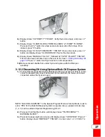
Page 42: ...11 1 Display shows DISPOSE and then PUMP X DONE Press X button display shows CLOSE DRAIN Close drain 1 12 2 Display shows MANUAL FILL VAT or FILL VAT FROM BULK if so equipped followed by IS POT FILLED...

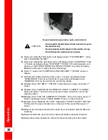
Page 43: ...9 2 2 Release cover latch and hinge back cover on oil disposal shuttle Make sure crumb catcher is in place 3 3 Roll oil disposal shuttle under fryer until it stops Make sure drain aligns with opening...

Page 44: ...n display Make sure drain pan is empty before proceeding 6 6 Press button and IS DISPOSAL UNIT IN PLACE YES NO shows in display 7 7 With discard shuttle rolled into place press button and display show...

Page 45: ...1 12 2 4 4 D Diis sc ca ar rd d O Oiill U Us siin ng g O Op pt tiio on na all O Oiill D Diis sc ca ar rd d S Sh hu ut tt tlle e O OD DS S 4 45 50 0 W Wiit th h p pr ro ollo on ng ge ed d u us se e t...

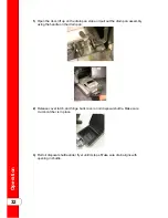
Page 46: ...out the drain pan assembly using the handle on the drain pan 2 2 Release cover latch and hinge back cover on oil disposal shuttle Make sure crumb catcher is in place 3 3 Roll oil disposal shuttle unde...

Page 47: ...PAN YES NO may show in display Make sure drain pan is empty before proceeding To reduce risk of fire or electrical shock do not empty more than one full vat or two split vats at one time 6 6 Press bu...

Page 48: ...tle to disposal container 1 14 4 Press down on top of brake to secure unit in place 1 15 5 Disconnect fitting from top of ODS and connect to disposal container 1 16 6 Using the power cord on the back...

Page 49: ...ol and then press and hold switch on container controls to pump oil from shuttle to the container 1 19 9 Once shuttle is empty release switch and unplug the electrical cord and wrap back onto the hook...

Page 50: ...te er r P Pa ad d In order to assure good oil pumping performance the filter pad or paper should be changed at least once per day However in stores open 24 hours a day the pad should be changed twice...

Page 51: ...Operation 37...

Page 52: ...oiill u us se e c ca ar re e t to o p pr re ev ve en nt t s sp plla as sh hiin ng g o or r b bu ur rn ns s c co ou ulld d r re es su ullt t 3 3 Lift the pan cover from the drain pan 4 4 Lift the crumb...

Page 53: ...t drain pan bottom screen crumb catcher and the retaining ring are thoroughly dry before placing filter pad into pan as water will dissolve the filter pad 9 9 Reassemble in reverse order placing the b...

Page 54: ...eaned periodically U Us se e p pr ro ot te ec ct tiiv ve e g gllo ov ve es s w wh he en n r re em mo ov viin ng g t th he e b ba as sk ke et t r re es st t T Th he e b ba as s k ke et t r re es st t m...

Page 55: ...t tiio on ns s o on n t th he e c clle ea an ne er r I If f s so ollu ut tiio on n c co om me es s iin n c co on nt ta ac ct t w wiit th h y yo ou ur r e ey ye es s r riin ns se e t th ho or ro ou ug...

Page 56: ...a av vo oiid d b bu ur rn ns s w wh he en n p po ou ur riin ng g h ho ot t s so ollu ut tiio on n w we ea ar r g gllo ov ve es s a an nd d p pr ro o t te ec ct tiiv ve e g ge ea ar r a an nd d t ta ak...

Page 57: ...5 Place a three gallon clear plastic bucket or a full sized meat pan under the drain valve 6 6 Use step 4 in the filter menu to drain the cold soak cleaning solution into the bucket or pan NOTE Use t...

Page 58: ...lt te er r p pa an n iis s m mo ov ve ed d w wh hiille e f fu ullll o of f o oiill u us se e c ca ar re e t to o p pr re ev ve en nt t s sp plla as sh hiin ng g o or r b bu ur rn ns s c co ou ulld d r...

Page 59: ...149 C shows in the right display For example REC 5 30 means it took 5 minutes and 30 seconds for the oil temperature to recover to 300 F 149 C from 250 F 121 C 3 3 1 18 8 2 2 F Fiillt te er r B Bu ut...

Page 60: ...15 Clean Out Mode page 41 Every change of oil Inspect filter pan O rings 3 17 Check Re place Drain Pan O Rings page 43 Quarterly Clean blower and vents 3 20 Clean Blower Vents page 46 Semi annually 3...

Page 61: ...n each blower opening 7 7 Clean the vent slots on the inside of rear panel and then replace panel 8 8 Reattach the gas line and turn the shutoff handle counterclockwise to turn on the gas and reconnec...

Page 62: ...Operation 48...

Page 63: ...t NOTE Not all Information Mode functions are discussed in this section To ensure proper operation of fryer please consult Henny Penny Corp before changing any of these settings For more information o...

Page 64: ...ft timer 1 LED is flashing PRODUCT FRY L1 shows in displays If the right timer 2 LED is flashing PRODUCT FRY R2 shows in displays 4 4 Press the down arrow to start viewing the cook data Function Displ...

Page 65: ...topped before DONE QUIT CK TUE 2 Cook Cycles for Product 1 COOK 1 TUE 17 Cook Cycles for Product 2 COOK 2 TUE 9 Cook Cycles for Product 3 COOK 3 TUE 5 Cook Cycles for Product 4 COOK 4 TUE 0 Cook Cycle...

Page 66: ...oduct 4 to view previous batch of oil Ex OIL 1 13 DAYS 4 4 5 5 5 5 R Re ev viie ew w U Us sa ag ge e The Review Usage section provides accumulated info since the data was last reset 1 1 Press the righ...

Page 67: ...1 16 6 U US SB B S Su up pp po or rt t 1 1 Press the down arrow and display shows REPORTS type of report PRINT This will print the type of report chosen To select a report press button 2 2 Press the...

Page 68: ...Information Mode 54...

Page 69: ...ge e P Pr ro od du uc ct t N Na am me es s 3 3 Use the up or down arrow to scroll through the 40 products or press the desired product button 4 4 Press the right arrow and NAME shows in the left displ...

Page 70: ...n the display at this time When the timer counts down to 2 30 the alarm sounds After alarm time is set press the right arrow and ALRM 2 shows in display and a second alarm can be programmed Q Qu ua al...

Page 71: ...n the display along with the full heat value in seconds which means the heat is on as soon as a timer is pressed for the programmed length of time Press the product buttons or the up or down arrow to...

Page 72: ...Product Program Mode 58...

Page 73: ...he displays NOTE If a bad code is entered a tone sounds and BAD CODE shows on the display Wait a few seconds the controls revert back to the cook mode and repeat the above steps To exit from the Speci...

Page 74: ...Pad Reminder Time XX HRS S SP P 1 11 1 Clean Out Time XX MIN S SP P 1 12 2 Clean Out Temperature XXX F or C S SP P 1 13 3 Cooking User IO After Cook Cycle display shows previous menu item or S SP P 1...

Page 75: ...t display Press the up or down arrow or product buttons to ad just the speaker volume 10 being loudest and 1 being the most quiet SP 5 Audio Tone Press and release the right arrow until SP 5 TONE flas...

Page 76: ...ds of french fries a load of chicken equals 1 1 2 1 8 1 8 1 4 1 Product No Cook Cycles Cycle Count Fish 2 1 2 French Fries 8 1 8 Chicken 4 1 4 M MI IX XE ED D If MIXED is selected press the right arro...

Page 77: ...t is filtered F Fu ullll V Va at t If unit is a full vat SP 8A and FULL VAT FILTER CYCLES shows in the left display and the number of cook cycles between filters shows on the right display 0 to 99 Use...

Page 78: ...anguage NOTE By settings a 2nd language in the controls 2 languages can now be chosen by pressing the program button during normal opera tion One language shows in the right display Pressing selects t...

Page 79: ...3 used to access Product Programming and Level 2 Program Mode Press and release the right arrow until SP 25 CHANGE MGR CODE 1 YES flashes in the display Press product 1 and ENTER NEW CODE P DONE I QU...

Page 80: ...of peak operations during which the FILTER NOW message will not appear may be programmed into the fryer There are three groupings of days Monday thru Friday M F Saturday SAT and Sunday SUN Within eac...

Page 81: ...lay Use the product buttons to set the date in the right display 5 5 Press the right arrow and CS 2 ENTER TIME flashes in the left display and the time flashes in the right display Press the up or dow...

Page 82: ...h S St ta at t F Fiillt te er r C Co on nt tr ro oll M Mo od de es s The Data Logging Heat Control Tech Stat and Filter Control Modes are advanced diagnostic and program modes mainly for Henny Penny u...

Page 83: ...the BIB BIB oil line is clogged or collapsed Check BIB line Filter pan needs cleaned Clean filter pan and change paper or pad Oil foaming or boiling over top of vat Water in oil Drain and clean oil Im...

Page 84: ...r r p pu um mp p m mo ot to or r s s m ma an nu ua all r re es se et t p pr ro ot te ec ct tiio on n d de ev viic ce e 7 7 2 2 E Er rr ro or r C Co od de es s In the event of a control system failure...

Page 85: ...t fan failure low voltage Have draft fan checked low voltage going to fan Flue or hood obstruction Check the fryer flue and hood system for obstruction E 20 D IGNITION FAILURE Failure to ignite no fla...

Page 86: ...ing or disconnected Have the jumper wire checked on the PC board at drain switch interlock position E 83 A Pressure too high Check filter system in vat 1 E 83 B Pressure too high Check filter system i...

Page 87: ...Troubleshooting 73...

Page 88: ...Troubleshooting 74...

Page 89: ...blank page...

Page 90: ...yp pe en nn ny y c co om m I In ns siid de e t th he e U U S S 1 1 8 80 00 0 4 41 17 7 8 84 40 05 5 t te ec ch hn niic ca alls se er rv viic ce es s h he en nn ny yp pe en nn ny y c co om m O Ou ut t...

Reviews: