background image

Model EEG-241, 242, 243, 244

14

Aug. 2014

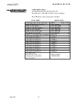
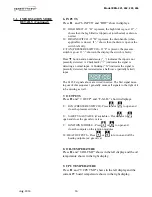
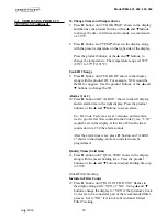
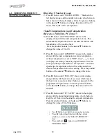
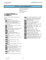
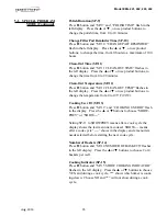
4.  OIL STATS 

(info of current oil and avg. of last 4 batches of oil)

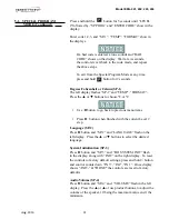
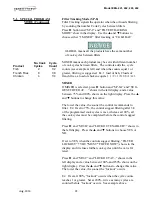
Press  ►  and “4. OIL STATS” show in displays.

Press ▼  button to start viewing the cook data.

Press and hold a product button (1 to 4) to view the data from 

one of the previous 4 batches of oil used.

Press        to view oldest oil data:   

  Ex: OIL-4    14 DAYS

Press         to view 3rd oldest oil data:      Ex: OIL-3    12 DAYS

Press         to view 2nd oldest oil data:     Ex: OIL-2    15 DAYS

Press         to view previous batch of oil:  Ex: OIL-1    13 DAYS

3-1.   INFORMATION MODE

         DETAILS (Continued)   

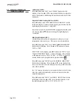
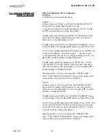
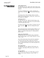
Start date of new oil


NEW OIL     

MAR-23  

Number of days oil in use 

(L/R) OIL USE 

4 DAYS

Number of filters on this oil 

(L/R) FILTERED     

4

Number of times filter skipped 

(L/R) SKIPPED        

0

Number of cook cycles on this oil 

(L/R) TOT CK  

38

Average number of days per oil change  

(L/R) AVG DAYS


PER OIL CHANGE   13.8 DAYS

Average number cook cycles per oil change  (L/R) AVG CKS PER


OIL CHANGE  

388 CKS


FUNCTION                                         DISPLAY EX:

To obtain the most accurate oil information, use 

the “3.DISPOSE” step in the Filter Menu (press 

and hold          ) to drain the oil from the vat.

Summary of Contents for EVOLUTION ELITE EEG-241

Page 1: ...TECHNICAL M A N U A L REGISTER WARRANTY ONLINE AT WWW HENNYPENNY COM Evolution Elite Gas Open Fryer MODEL EEG 241 EEG 242 EEG 243 EEG 244 ...

Page 2: ......
Page 3: ...tails 11 Section 4 PRODUCT PROGRAM MODE 17 4 1 Modifying Product Settings 17 Section 5 LEVEL 2 PROGRAMMING 20 5 1 Special Program Mode 20 5 2 Clock Set 29 5 3 Data Logging Heat Control Tech Stat Filter Control Modes 29 5 4 Tech Mode 30 5 5 Stats Mode 36 5 6 Do Not Disturb 37 Section 6 MAINTENANCE SECTION 38 6 1 Introduction 38 6 2 Maintenance Hints 38 6 3 Preventive Maintenance 38 6 4 Control Pane...

Page 4: ...CE SECTION Continued 6 8 Solenoid Valves 45 6 9 Filter Pump Motor 48 6 10 JIB Pump 50 6 11 Blower Replacement 51 6 12 Filter Beacon 52 6 13 Air Pressure Switches 53 6 14 Pilot Replacement 54 Section 7 PARTS SECTION 7 1 Parts 63 TABLE OF CONTENTS Section Page ...

Page 5: ...r usage is described below SAFETY ALERT SYMBOL is used with DANGER WARNING or CAUTION which indicates a personal injury type hazard NOTICE is used to highlight especially important information CAUTION used without the safety alert symbol indicates a potentially hazardous situation which if not avoided may result in property damage CAUTION indicates a potentially hazardous situation which if not av...

Page 6: ...ubleshooting table 3 Review all possible causes Then one at a time work through the list of corrections until the problem is solved 4 Refer to the maintenance procedures in the Maintenance Section to safely and properly make the checkout and repair needed 1 3 TROUBLESHOOTING If maintenance procedures are not followed correctly injuries and or property damage could result ...

Page 7: ...x E 10 Hight limit Let unit cool down 15 20 minutes push up on metal reset button under right side of the controls if high limit does not reset high limit must be replaced Vat is under filled JIB is low or empty JIB oil line is clogged or collapsed Filter pan needs cleaned Fill the JIB Check JIB line Clean filter pan and change paper or pad 7 1 TROUBLE SHOOTING Continued ...

Page 8: ... not reassembled correctly Tighten all filter line connections Change filter paper or pad Refer to assembly instructions on inside door Bubbles in oil during entire filtering process Filter pan not completel engaged Filter pan clogged Damaged O ring on filter line receiver on fryer Make sure filter pan return line is pushed completely into the receiver on the fryer Clean pan and change paper or pa...

Page 9: ...be should be checked E 6A Temperature probe open Turn switch to OFF position then turn switch back to ON if display shows E 6A the temperature probe should be checked E 6B Temperature probe shorted Turn switch to OFF position then turn switch back to ON if display shows E 6B the temperature probe should be checked E 10 Hight limit Let unit cool down 15 20 minutes push up on metal reset button unde...

Page 10: ...E 20 D persists check gas line connections check gas shutoff valve check ignition module check gas valve check flame sensor gap check gas valve and check ignition module wiring Clear obstruction from hole E 21 Slow heat recovery Have a certified service technician check the fryer for correct voltage to the unit have heat circuit checked have unit checked for loose or burnt wire E 22 NO HEAT CHECK ...

Page 11: ...at drain switch interlock position E 83 A Pressure too high Check filter system in Vat 1 E 83 B Pressure too high Check filter system in Vat 2 E 83 C Pressure too high Check filter system in Vat 3 E 83 D Pressure too high Check filter system in Vat 4 E 83 E Pressure too high Check filter system in Vat 5 E 83 J Bulk JIB FILL switch ON when pressure too high Check JIB fill valves E 83 R Bulk Dispose...

Page 12: ...to recover to 300 F 149 C from 250 F 121 C Cook Cycles Remaining before Filtering 1 Press and release either button and the left display shows COOKSREMAINING and the right display shows the number of cook cycles before the next auto filter For example means after 3 more cook cycles on the left vat the controls asks the operator if they are ready to filter or not But 6 more cook cycles remain on th...

Page 13: ...that the controls recorded Press and the next latest error code information can be seen Up to 10 error codes B to K can be stored in the E LOG section 3 1 INFORMATION MODE DETAILS 1 E LOG 9 CPU TEMP 2 LAST LOAD 10 COMMUNICATION INFO 3 DAILY STATS 11 ANALOG INFO 4 OIL STATS 12 ACTIVITY LOG 5 REVIEW USAGE 13 OIL LEVELS 6 INPUTS 14 PUMP VALVE INFO 7 OUTPUTS 15 AIF INFO 8 OIL TEMP Not all Information ...

Page 14: ...ata 3 1 INFORMATION MODE DETAILS Continued FUNCTION DISPLAY EX Product Last product cooked PRODUCT FRY L1 Time of day the last Cook Cycle was started STARTED FEB 4 2 25P Actual Elapsed cook Time Real seconds ACTUAL TIME 1 06 Programmed cook Time PROG TIME 1 00 Max Temp during Cook Cycle MAX TEMP 350 F Min Temp during Cook Cycle MIN TEMP 313 F Avg Temp during Cook Cycle AVG TEMP 322 F Heat On perce...

Page 15: ...E 4 Number of times oil added L R ADD OIL TUE 4 Number of times oil discarded L R DISPOSE TUE 0 Oil temperature recovery time L R RECOVERY TUE 1 45 Total number of cook cycles that day L R TOT CK TUE 38 Number of cycles stopped before DONE QUIT CK TUE 2 Cook Cycles for Product 1 TUE COOK 1 17 Cook Cycles for Product 2 TUE COOK 2 9 Cook Cycles for Product 3 TUE COOK 3 5 Cook Cycles for Product 4 TU...

Page 16: ...L 2 15 DAYS Press to view previous batch of oil Ex OIL 1 13 DAYS 3 1 INFORMATION MODE DETAILS Continued Start date of new oil NEW OIL MAR 23 Number of days oil in use L R OIL USE 4 DAYS Number of filters on this oil L R FILTERED 4 Number of times filter skipped L R SKIPPED 0 Number of cook cycles on this oil L R TOT CK 38 Average number of days per oil change L R AVG DAYS PER OIL CHANGE 13 8 DAYS ...

Page 17: ...er of times oil discarded L R DISPOSE 1 Total number of cook cycles L R TOT CK 38 Number of cycles stopped before DONE QUIT CK 2 Cook Cycles for Product 1 COOK 1 17 Cook Cycles for Product 2 COOK 2 9 Cook Cycles for Product 3 COOK 3 5 Cook Cycles for Product 4 COOK 4 0 Cook Cycles for Product 5 COOK 5 0 Cook Cycles for Product 6 COOK 6 6 Cook Cycles for Product 7 COOK 7 0 Cook Cycles for Product 8...

Page 18: ...s detected as a half wave partially failed input The H D F signals above are wired in series The first signal miss ing out of this sequence l generally causes all signals to the right of it to be missing as well 7 OUTPUTS Press and 7 OUTP and F S I H show in displays F FAN PRESSURE SWITCH Press or to open and close the pressure switches S SAFETY GAS VALVE if available Press or to open and close th...

Page 19: ...lashing letter changes to a B Press it again and the flashing letter changes to a C Once the desired letter shows in the display press button to continue to the next letter and repeat the procedure Press and hold the right X button to exit Program Mode or press button to continue on to COOK TIME Assign Button 6 Press button until ASSIGN BTN shows in the display along with the product ex NUGGETS If...

Page 20: ...e in the right display Press the product buttons or the and buttons to set an alarm Ex If a Cook Cycle was set at 3 minutes and an alarm was to go off after 30 seconds into the Cook Cycle 2 30 would be set in the display at this time When the timer counts down to 2 30 the alarm sounds After the alarm time is set press button and ALRM 2 shows in the display and a second alarm can be programmed Qual...

Page 21: ...isplay and setting cannot be programmed This is the average cooking temperature for each product The timer speeds up at temperatures above this setting and slows down at temperatures below this setting Press the product button or the and buttons to change this value 16 Press button until FULL HT shows in the display along with the full heat value in seconds which means the heat is on as soon as a ...

Page 22: ...13 Cooking User IO After Cook Cycle display shows previous menu item or SP 14 Number of Baskets 2 BASKETS or 4 BASKETS SP 15 Show Cooking Indicator YES or NO 5 1 SPECIAL PROGRAM MODE Used to access the following Special Program Mode Clock Set Data Communication Heat Control SECTION 5 LEVEL 2 PROGRAMMING SP 16 2nd Language English Russian Swedish SVENSKT German DEUTSCHE Portuguese Spanish ESPANOL a...

Page 23: ...ht display To reset the controls to factory default settings press and hold button and control counts down IN 3 IN2 IN 1 Once display shows INIT DONE the controls are reset to factory defaults Audio Volume SP 4 Press button and SP 4 and VOLUME flash in the left display Press the or or use product buttons to adjust the volume of the speaker 10 being the maximum value and 1 the minimum 5 1 SPECIAL P...

Page 24: ... temperature when not in use This savies on oil and utilities Press button and SP 7 and IDLE MODE ENABLED flash in the left display Press the or buttons to choose YES or NO With YES in the display press button and SP 7A and USE 0 FOR IDLE flash on the left display Press the or buttons to select YES or NO If YES is selected an Idle Mode can be programmed in product button Press button and SP 7B and...

Page 25: ...e control recommends to filter Ex If set to 75 the control suggest filtering after 3 4 of the programmed cook cycles is met whereas at 100 all the cook cycles must be completed before the control suggest filtering Press and SP 8B and LOCKOUT ENABLED shows in the left display Press the and buttons to choose YES or NO If set to YES when the controls suggest filtering FILTER LOCKOUT YOU MUST FILTER N...

Page 26: ... and RGHT VAT LOCKOUT CYCLES and the number of cook cycles before filter lock out shows on the right display 0 to 99 Use and or product numbers to change this number Once this number of cook cycles is reached FILTER LOCK OUT YOU MUST FILTER NOW shows in the display and it refuses further cook cycles until the vat is filtered Full Vat If unit is a full vat SP 8A and FULL VAT FILTER CYCLES shows in ...

Page 27: ...play Press the or or use product buttons to change the temperature from 0 to 195o F 90o C Cooking User IO SP 13 Press button and SP 11 and COOKING USER IO flash in the display Press the or buttons to choose SHOW PREV or SHOW Setting SP 11 to SHOWPREV means after a cook cycle the display shows the last menu item cooked SHOW means after a cook cycle shows in the display and a menu item needs selecte...

Page 28: ...n twice during normal opera tion One volume setting shows in the left display NONE to 10 10 being the loudest and the second volume shows in the right display To select the volume press the button under the desired volume Engery Save Mode SP 18 Press button and SP 18 ENERGY SAVE ENABLED flashes in the left display Press the or buttons to choose YES or NO If set to YES during times of non use the f...

Page 29: ...ISP or NO DISP Set to YES DISP if the oil is pumped from the vats to an outside oil reservoir when disarding the oil Otherwise set SP 23 to NO DISP Serial Number Log SP 24 Press button and SP 24 and S N EDIT flash in the displays along with the serial number of the unit THIS SERI AL NUMBER SHOULD MATCH THE SERIAL NUMBER ON THE DATA PLATE ON THE DOORS IF NOT IT CAN BE RECORDED Program Code Change S...

Page 30: ...NEW CODE P DONE I QUIT shows in display Press same code buttons If satisfied with code press CODE CHANGED shows in display If not satisfied with code press and CANCEL shows in display then reverts back to SP 26 and CHANGE USAGE CODE 1 YES Now the above steps can be repeat ed Dispose Requires Code SP 27 Press button and SP 27 DISPOSE REQUIRES CODE flashes in the left display Press the or buttons to...

Page 31: ...IME flashes in the left display and AM or PM flashes in the right display Use the or buttons to choose AM or PM 7 Press button and CS 3 TIME FORMAT flashes in the left display and 12 HR or 24 HR shows in the right display Use the or buttons to choose a 12 hour time format or a 24 hour time format 8 Press button and CS 4 DAYLIGHT SAVING TIME flashes in the left display Use the or buttons to choose ...

Page 32: ...bration Offset T 12 Right Temp Probe Calibration Offset T 13 Right Level 1 Probe Calibration Offset T 14 Right Level 2 Probe Calibration Offset T 15 CPU Control Temp Calibration Offset Highest T 16 View A D Channel T 17 Inputs T 18 Outputs S H S H T 19 Basket Lifts T 20 AIF Info T 21 Pumps and Valves T 22 Recovery Test Valves T 23 Heat Err Enabled T 24 Change Tech Code T 25 Total Initialization No...

Page 33: ... Press to view software version T 2 FRYER TYPE GAS or ELEC T 3 PUSH BUTTON TEST Press any of the control buttons to test operation You should hear a beep and the LED should light and or a display T 4 ALL ON DISPLAY TEST Press any of the product buttons and all the LEDs and display segments should light T 5 SEGMENTS TEST Press button to view the different segments of the display characters T 6 DIGI...

Page 34: ... FAN PRESSURE SWITCH If F is present the pressure switch is good If shows in the display the switch is faulty Press button and an underscore _ indicates the input is not presently detected A Checkmark indicates the signal is detecting a normal input A blinking X indicates the signal is presently detected but is detected as a half wave partially failed input The H D F signals above are wired in ser...

Page 35: ...in displays Press to open and close the return valve DcRc means valve is closed DcRo means valve is open Driven by the control board Press button and DISCARDc and JIBFILLc shows in the displays Driven by the AIF board Press to open and close the RTI discard valve display shows DISCARDo when open Press to open and close the RTI JIB fill valve display shows JIBFILLo when open Press button and PUMP F...

Page 36: ...x shows in the displays These displays shows which controls are using the filtering system USE 0 not in use USE 7 used by AIF USE 1 to 5 used by control PCB Press button and CPU POSN and 1 OF 3 ex shows in the displays These displays shows which controls are plugged into which port on the AIF board For example the left control should be plugged into port 1 and on a 3 control fryer shows 1 OF 3 on ...

Page 37: ...sent DI Discard Valve DIo Disc valve open DIc closed if present JF JIB Fill Valve JFo JIB fill valve open JFc closed Press button and REQ F_J_ and N_DI_JF_ shows in the displays AIF Board Outputs Requested by the Control Board Current outputs status from AIF board F Filter Pump Fx Filter pump is on J JIB Pump Jx JIB pump is on N New Oil Pump Nx New oil pump on if present DI Discard Valve DIo Disc ...

Page 38: ...elt Cycle Hours ST 7 Right Vat Cook Cycle Hours ST 8 Right Vat Idle Hours ST 9 Power Ups Count ST 10 Error Counts ST 11 Left Vat Heat On Hours ST 12 Right Vat Heat On Hours ST 13 Highest Left Vat Oil Temperature ST 14 Highest Right Vat Oil Temperature ST 15 Highest CPU Temperature ST 16 System RAM Fade Count ST 17 Cook RAM Fade Count ST 18 Product RAM Fade Count ST 19 Stat RAM Fade Count ST 20 RAM...

Page 39: ...play 3 Enter code 1 2 3 first 3 product buttons 4 DO NOT DISTURB ENABLED flashes in the left display and YES or NO appears in the right display Press the or buttons to choose YES or NO 5 Press button and M F 1 shows in the left display and the time flashes in the right display Press the or or use product buttons to change the time 6 Press button and M F 1 shows in the left display and A or P flash...

Page 40: ...n result from splashing hot oil To ensure a long life of the fryers and their components regular maintenance should be performed Refer to the chart below SECTION 6 MAINTENANCE 6 1 INTRODUCTION 6 2 MAINTENANCE HINTS 6 3 PREVENTIVE MAINTENANCE Frequency Action Daily Filter the oil See Daily Filtering Instructions Section in Operator s Manual Daily Change Filter Pad See Changing Filter Pad Section in...

Page 41: ...ws securing the control panel 3 Pull the top of the panel down allowing the panel to be supported by the 2 brackets in the slots in the control shroud If changing control panel continue onto step 5 4 If changing the menu card loosen the tape securing the menu card at the bottom side of the control panel and pull menu card from panel Carefully slide changed menu card back into slot in panel and sec...

Page 42: ...ld which covers the high limit control 4 Mark and disconnect the wires located on the high limit control 5 Using a 3 8 wrench remove the nuts 6 Remove the clamp bars 7 Slide the high limit control off of mounting studs 8 Install the new control in reverse order To avoid electrical shock or property damage move the POWER switch to OFF and disconnect main circuit breaker or unplug cord at wall recep...

Page 43: ...ontrol board see Control Board Replacement 2 Press on the switch from the inside of the fryer to release from the metal shroud 3 Mark and disconnect the wires from the switch 4 Connect the wires onto the new switch on the correct terminals 5 Press back into factory location ...

Page 44: ...hm check can be performed also See chart below Checkout To avoid electrical shock or property damage move the power switch to OFF and disconnect main circuit breaker or unplug cord at wall receptacle 1 Using a Phillip s head screwdriver or cordless drill loosen the screw securing the top of the control panel and secure control panel in the slots of the shroud 2 Pull the probe connector from the co...

Page 45: ...ker or unplug cord at wall receptacle 2 Using a 3 8 socket remove the 2 screws securing the burner jet bracket and remove bracket 3 Pull both burner jets from unit 4 Using a 1 2 wrench remove the nut on the compression fitting and remove the temperature probe from the vat 5 Using a terminal extractor remove the probe terminals from the connector and pull remove probe from unit 6 7 TEMPERATURE PROB...

Page 46: ...new ferrule on the new temperature probe and insert the temperature probe into the compression fitting See drawing below 7 Using the probe gauge in the kit follow the instructions on drawing below 8 Hand tighten compression nut and then a half turn with wrench Excess force will damage temperature probe ...

Page 47: ...eturn to normal operation Each vat has a solenoid plumbed into the oil return lines They are normally closed but open when power is supplied such as the controls are filling the vats To avoid electrical shock or property damage move the power switch to OFF and disconnect main circuit breaker or unplug cord at wall receptacle 1 Remove both top and bottom rear panels or a side panel depending upon t...

Page 48: ...Replacement 1 Using an adjustable wrench loosen the front and rear fit tings to solenoid 2 Remove the conduit from the fryer and pull the solenoid assembly from the fryer 3 Remove the conduit from the solenoid 6 8 SOLENOID VALVES Continued ...

Page 49: ...o the new solenoid using pipe sealent on the threads 5 Reattach the conduit to the new solenoid threading the wires through the conduit 6 Reattach the solenoid assembly to the fryer 7 Reattach the conduit to the fryer and connect the wires to the fryer using wire nuts 8 Replace rear side panels or rear panels and reconnect power to the fryer ...

Page 50: ... 6 Use a 3 8 socket or wrench and remove the four nuts and washers from the pumps feet 7 Pull the pump off of the studs 8 Remove the wire nuts 9 Wire the new pump into the existing wires 10 Place the pump onto the studs Be sure to have the shield box in place on the studs before placing the pump onto studs 11 Tighten the pump nuts and washers onto the feet of the pump 12 Reconnect fittings 13 Repl...

Page 51: ...screw is located on the back side of the flue 4 Cut zip ties that are holding the wires to the blower Remove the wire nuts from the wires 5 Remove blower 6 Reconnect new blower wires to the existing wires with wire nuts 7 Tighten the new blower onto the flue with the two screws 8 Zip tie wires back to the blower To avoid electrical shock or property damage move the POWER switch to OFF and disconne...

Page 52: ...e right or left side panel for end vats or hinge down the control panel for center vats 2 Pull apart the light by pulling on the rear of the light and re moving the front part of the light from the front of the fryer 3 Locate and cut the light wires and pull the light from unit 4 Connect new light wires using wirenuts and install light in reverse order 5 Restore power to the unit 6 12 FILTER BEACO...

Page 53: ...t 2 Remove the lower back shroud See back shroud removal 3 Remove the pressure switch mounting cover from the frame 4 Remove the vacuum hose from switch 5 Using a phillips bit or screwdriver remove the two screws securing switch to the cover 6 Disconnect the wires on the switch 7 Replace switch in reverse order ...

Page 54: ...ove the flame sensor wire 5 Remove the two screws securing the pilot to the burner assembly The right hand screw will have the ground wire 6 Disconnect the pilot wire located in the orange rubber sleeve 7 Using a 7 16 wrench loosen the pilot tube from the pilot 8 Disconnect the flame sensor 9 Replace pilot in reverse order 10 When screwing the pilot back to the burner assembly be sure to connect t...

Page 55: ...stocked by your distributor and will be sent out when your order is received Other parts will be ordered by your distributor from Henny Penny Corpora tion Normally these will be sent to your distributor within three working days 7 6 WARRANTY All replacement parts except lamps and fuses are warranted for 90 days against manufacturing defects and workmanship If damage occurs during shipping notify t...

Page 56: ...POWER SWITCH 1 9 82016RB ASSY EVOL ELITE FRYER CONTROL 1 well 9 84417RB ASSY EVOLUTION ELITE AUTO CONT 1 well 9 140402 KIT EEX CONTROL W THUMB DRIVE Smart Touch 1 vat 10 152634 DRAIN PAN ASSY 1 11 81915 BASKET 1 2 SIZE BLK FRONT SUPP A R 11 85136 BASKET FULL SIZE BLACK FR SPRT A R 12 152487 CABLE USB PORT AND 1 vat 12 152488 CAP USB 1 vat 13 78992 ASSY JIB TUBE QUICK DISC 1 14 FP05 017 QUICK DISCO...

Page 57: ...WELD ASSY CRUMB CATCHER 1 4 85503 WELD ASSY FILTER WEIGHT 1 5 85519 FILTER SECTION 1 6 95842 ASSY DRAIN PAN 1 7 19004 CASTER SWIVEL 2IN 4 8 SC01 009 SCREW 1 4 20 X 1 2 THD 4 wheel 9 NS04 005 LOCKNUT1 4 20 4 wheel 10 86349 O RING 116 SUCTION LINE 3 11 12074 SMART FILTERS PAD 30 COUNT 1 11 12076 SMART FILTERS PAPER 1 1 Recommend Parts A Truck Stock B Dist Stock not shown A R As Required ...

Page 58: ... short 93355 ASSY LH DOOR short 93355 ASSY LH DOOR short 93356 ASSY RH DOOR 93356 ASSY RH DOOR Door Hinge Chart Door Top Hinge Door Bottom Hinge Door Bottom Hinge Frame Bushing 150300 93370 93369 150624 39752 93355 93370 93369 85409 39752 93355 93370 93369 85409 39752 93356 93369 93370 150625 39752 EEG 164 Door Break Down EEG 163 Door Break Down Recommend Parts A Truck Stock B Dist Stock not shown...

Page 59: ...BURNER NAT 4 burner 3 76921 002 ORIFICE MAIN BURNER LP 4 burner 4 FLEX TUBE see flex tube chart for length part number 5 84391 ASSY TRANSFORMER 120V 1 well 5 83977 TRANSFORMER 208 240 50 60 75VA 1 well 5 84135 ASSY 24V 240V 75VA TRANSFORMER 1 well 5 83976 TRANSFORMER 120V 50 60HZ 75VA 1 well 6 82491 TUBE 1 4 X 12 FLEX SS PILOT 1 2 well 7 89624 001 CONTROL WATLOW HL 1 vat 7 89624 002 CONTROL WATLOW...

Page 60: ...T 140283 KIT EEG16X FRYER SUPPLY Chili s 140289 KIT REPL FULL POT ASSY EEG2XX 140290 KIT NAT TO LP F UP TO 5000 FT 140291 KIT LP TO NAT F UP TO 5000 FT 140295 KIT EEG16X FRYER SPLY MAGGIANO 140296 KIT EEG16X 2XX NAT BASO PILOT 140297 KIT EEG16X 2XX LP BASO PILOT 140307 KIT EEG16X BULK DISPOSE FILL ...

Page 61: ...1 well 2 92963 002 BLOWER MOTOR FLUE EXHAUST 230V 1 well 3 FLEX TUBE see flex tube chart for length part number 4 152902 001 CORD POWER 1 5 151744 VALVE 120V SOLENOID 1 2NPT 1 vat 6 151725 ASSY POT CHECK VALVE 1 vat 7 97599 SVC PACK LV EE JIB RETRO 115V 1 7 97600 SVC PACK LV EE JIB RETRO 230V 1 5 Recommend Parts A Truck Stock B Dist Stock not shown A R As Required ...

Page 62: ...1 DRAIN VALVE ACTUATOR ASSY 1 vat 86157 DRAIN VALVE ACTUATOR ACTUATOR ONLY 1 vat 140244 DRAIN VALVE WITH O RING 2 NS03 103 NUT CASTLE 1 2 20 18 8 STEEL 1 vat 17255 PIN COTTER 1 vat 3 76948 O RING 325 1 vat 4 151106 ARM PIVOT 1 vat 5 PN01 012 CLEVIS PIN 1 4 X 1 IN SS 1 vat 6 151156 PIVOT BUSHING ROD LINKAGE 1 vat 7 150181 SPACER DRAIN ROD LINKAGE 1 vat 8 PN01 039 PIN COTTER 1 vat ...

Page 63: ...010 54 0 77523 011 10 0 77523 012 13 0 77523 013 14 0 77523 014 28 0 77523 015 32 0 77523 016 16 0 Recommend Parts A Truck Stock B Dist Stock not shown A R As Required 1 2 3 Item No Part No Description Quantity 1 See next page for part breakdown 2 87511 SWITCH DRAIN PAN 1 3 151686 002 HOSE OIL DISPOSE 34in 1 4 90506 001 VALVE CHECK SAE 12 3PSI A R 5 FP01 256 FTG 12 SAE 1 2 NPT A R 6 FP01 283 FTG 1...

Page 64: ...uantity 1 151534 001 ASSY FILTER PUMP MOTOR EEG16X 60HZ 1 67583 MOTOR 1 2 HP FILTER PUMP 1 17437 ASSY SUB PUMP 5 GPM 1 17476 SEAL KIT 1 1 151534 002 ASSY FILTER PUMP MOTOR EEG16X 50HZ 1 92850 MOTOR 1 2 HP FILTER PUMP 50HZ 1 17437 ASSY SUB PUMP 5 GPM 1 17476 SEAL KIT 1 ...

Page 65: ...90 008 P B T92 RELAY 12VDC COIL 30AMP 1 1 ME90 005 RELAY 12V OC COIL SPDT 1 2 84454RB ASSY EVOLUTION ELITE AIF PCB 1 3 77992 SWITCH PRESSURE 0 80 1 vat 4 77839 MODULE IGNITION NON CE 2 well 5 60818 RELAY 24VAC COIL 1 well Recommend Parts A Truck Stock B Dist Stock not shown A R As Required ...

Reviews: