STEAMY SAUNA HEATER: 1105- 901-0104 1105-1051-0104 1105-1201-0104 1105-1501-0104
CONTROL PANEL: 0518-2-151704
7013933
314 SKLE 44 D
Page 1: ...STEAMY SAUNA HEATER 1105 901 0104 1105 1051 0104 1105 1201 0104 1105 1501 0104 CONTROL PANEL 0518 2 151704 7013933 314 SKLE 44 D...
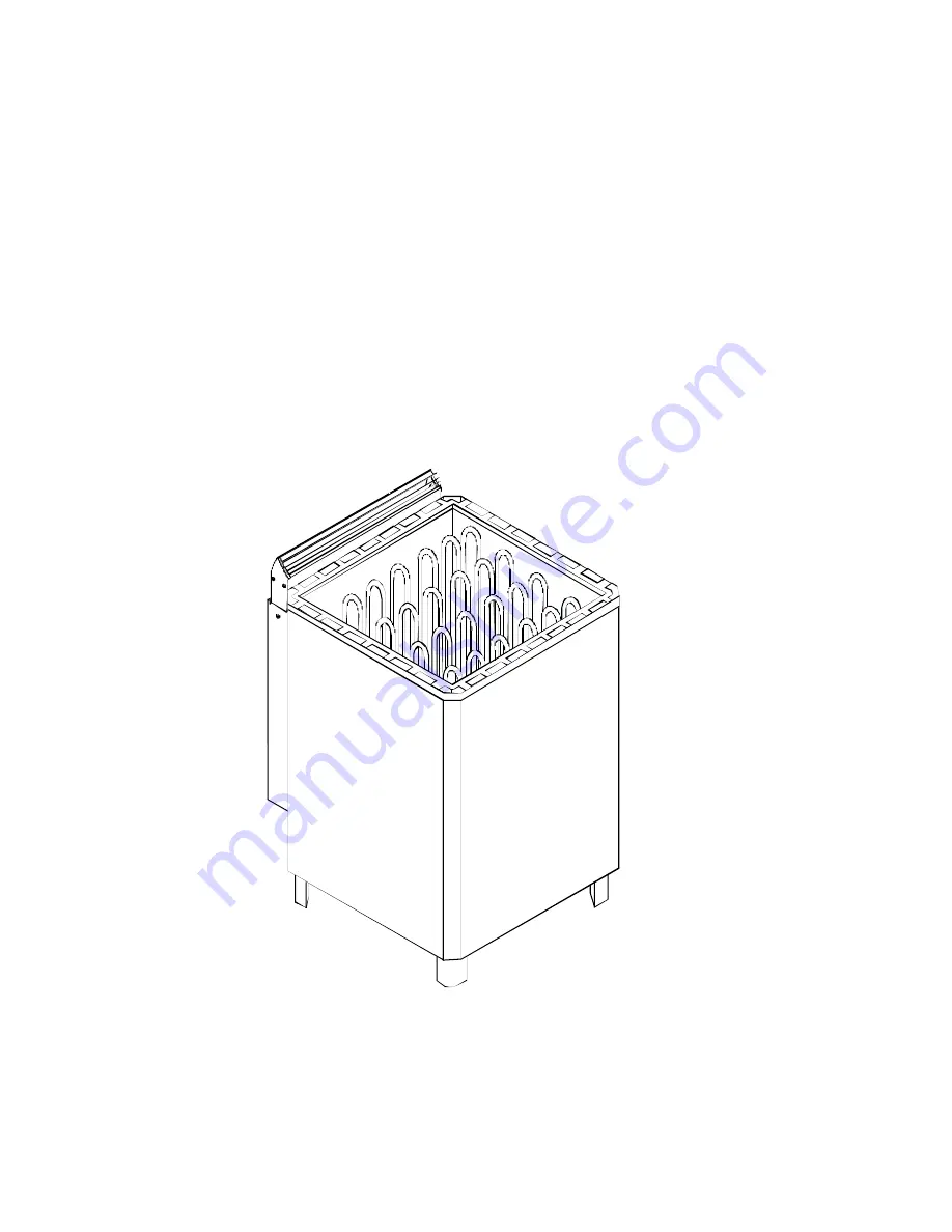
Page 2: ...distances to combustible ma terial indicated on the name plate of the heater and in table 1 and fig 1 The sauna heater can be placed on a wooden floor Do not protect the wall behind the heater with f...
Page 3: ...n the rock compartement Put the largest stones at the bottom Do not pack the stones tight but place them to allow good air circulation To prevent damage to the sau na unit the stones must be replaced...
Page 4: ...during the Pre set time and the Heating up time this enables pre heating without steam OPERATING INSTRUCTIONS NORMAL SAUNA Can be obtained by setting the timer dial to the first range from 1 to 6 hou...
Page 5: ...hat Steam generation is activated Remark Steam Bath in normal sence can not be achtived since the output from the generator alone is not big enough to rise the temperature to steam bath level 2 h F C...
Page 6: ...asure A min B min C min and H min table 1 Fig 1 1 Timer knob in control panel 2 Sensor unit 3 Heat resisting cable 4 Cable to control panel 5 Junction box 6 Connection cable to steamy unit 7 Fastening...
Page 7: ...7 heater control unit sensor ac input 400N 3N 5x6mm2 5x6mm2 6x1 5mm2...
Page 8: ...arried out by a qualified electrician in accordance with VDE 0100 section 703 The sauna is to be solidly connected to the net SENSOR INSTALLATION P N L N U1 N U 1 2 3 3 4 1 2 N 4 1 2 3 4 OLET 6 1 A2 A...
Page 9: ...L1L2 L3 N U V W Steamy unit Ofen 1 2 3 4 5 6 400V 3N 415V 3N Teho Effekt Input Leistung V imsus kW L mp vastukset V rmeelement Heating element Heizeelement Tennid 9 0 10 5 12 0 15 0 354 SKLE 17 F SEPC...