background image

Operating Instructions • CPK hybrid • 11-2021 • v04 • 106-29004

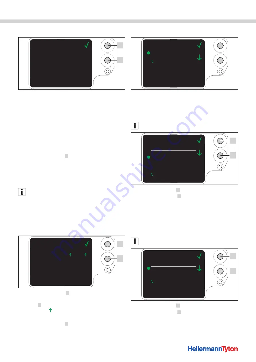
Settings in the main menu

17

8 .2  Status menu

00000005
1.70/ 8/ 3
01:11
00000013
28

06/02/2019

58

0000000

Counter reading
Tool software
Power-pack SW
Serial number
Temperature

Last service

Humidity

Cntr.rdng.lastSer

Status

1

2

The 

Status

 menu shows you the following status 

readings:
•  Counter reading
•  Software version of the CPK hybrid and an index number 

for the language version

•  Software version of the power pack
•  Serial number of the tool
•  Ambient temperature and humidity
•  Date of last service
•  Counter reading at last service


f

Press the Enter button 

 1 

.


;

The Main menu appears on the display.

8 .3  Settings menu

You use the 

Settings

 menu to set important parameters 

of the CPK hybrid.

Access to the 

Settings

 menu is protected by a three-digit 

access code that can be changed in the HT Data 

Management software, 

à

 "Changing the access code for 

the CPK hybrid" on page 23

. The default access code is 

000

.


f

Use the Select button 

in the 

Main menu

 to select the 

Settings

 menu.


f

Press the Enter button.


;

The prompt for the access code appears on the display.

0 0 0

Access code

Settings

1

2


f

Press the Select button 

 2 

.


f

After reaching the desired number, press the Enter 
button 

 1 

.


;

The selection   jumps forward one digit.


f

Repeat the setting until the desired access code is set.


f

Press the Enter button 

 1 

.


;

The 

Settings

 menu appears on the display.

Settings

Interruption front sensor
Check of binding

Back

8 .3 .1  Interruption front sensor

The 

Interruption front sensor

 setting enables you to 

decide how long the level sensor can remain busy 
without the 

Error, front cap

 message appearing on the 

display.

This function is intended for use with the device integrated 

into an automatic system.

0.0 sec.
0.3 sec.
0.5 sec.
0.7 sec.
0.9 sec.

Settings

Interruption front sensor
Level 1
Level 2
Level 3
Level 4
Level 5

Back

1

2


f

Use the Select button 

 2 

 to select the level.


f

Press the Enter button 

 1 

.


;

The setting changes to the level you selected.

8 .3 .2  Check of binding

The 

Check of binding

 setting enables you to decide 

whether or not the 

Error, binding force


message appears on the display, 

à

 "Display messages" on 

page 32

.

The binding check can also be set with the HTDM, 

à

 "Setting the binding check" on page 21

.

Check of binding
OFF
Error notification
Acknowledgement

Settings

Back

1

2


f

Use the Select button 

 2 

 to select the desired setting.


f

Press the Enter button 

 1 

.

Summary of Contents for Autotool CPK hybrid

Page 1: ...A u t o t o o l C P K h y b r i d TOC Cover Operating Instructions...

Page 2: ...2 Translation of the original operating instructions 3...

Page 3: ...ess at the workplace 9 2 5 2 Spare parts and accessories 9 3 Design and function 10 3 1 Overview 10 3 1 1 Scope of supply 10 3 1 2 Serial number 10 3 1 3 Checking scope of supply 10 3 2 Functional des...

Page 4: ...e HTML format 24 9 6 Update menu 25 9 6 1 Updating the firmware 25 9 6 2 Changing the password 26 9 6 3 Updating binding parameters 26 9 6 4 Installing other languages 26 9 7 Measurement environment m...

Page 5: ...Operating Instructions must be kept in the immediate vicinity of the workplace and must be available at all times to all operating personnel The operating company shall inform the operating personnel...

Page 6: ...s radiators cookers and refrigerators The risk of electric shock is higher when your body is earthed c Protect power tools from rain and moisture Water penetrating into a power tool increases the risk...

Page 7: ...instructions are in the enclosed manufacturer s document for the battery pack b Protect the battery pack from moisture Do not dip the battery pack into liquids Contact with liquids can cause damage t...

Page 8: ...e develops in the charger m Do not attempt to charge faulty battery packs n In areas where metal dust load is high do not use an AIR COOLED charger to charge battery packs 2 1 7 Service Have your powe...

Page 9: ...ted to carry out repairs and safety checks 2 5 Underlying hazards associated with use of the CPK hybrid 2 5 1 Cleanliness at the workplace Orderliness good lighting and cleanliness at the workplace al...

Page 10: ...rid 8 USB connecting cable A B separate delivery with power pack 9 Connecting cable for connecting power pack and CPK hybrid separate delivery with power pack 10 power pack CPK separate delivery 3 1 2...

Page 11: ...e user through the recommended fault diagnosis routine Troubleshooting on page 31 Process data of various kinds are collected during use These data can be analysed by PC software and used to document...

Page 12: ...battery pack with charger in dust proof packaging f Store electrical components tool power pack and battery pack with charger in impact absorbing packaging and separately from the accessories f Observ...

Page 13: ...o restore operational readiness press the start trigger once 6 2 2 Switching off f Press the battery pack on off button on the handle The battery pack switches to standby mode 6 3 Loading cable ties 1...

Page 14: ...in the display menu f Press the Enter button 1 f Press the Enter button 1 several times to return to the start screen f Check the LED status indicator 3 Troubleshooting on page 31 A printed short gui...

Page 15: ...CPK 001 1 2 3 f Press the Select button 2 f The binding quality 3 is indicated with a blue border f Press the Enter button 1 until the desired binding quality is reached The binding quality 3 is indic...

Page 16: ...the Enter button 1 to deactivate tension free cutting f Press the Select button 2 to finish configuring the settings 8 Settings in the main menu After switching on the CPK hybrid at the connected pow...

Page 17: ...isplay 0 0 0 Access code Settings 1 2 f Press the Select button 2 f After reaching the desired number press the Enter button 1 The selection jumps forward one digit f Repeat the setting until the desi...

Page 18: ...independent operation connect the tool to the PC directly with the optional smart cable Accessories and extras on page 37 f Launch the HT Data Management software The HT Data Management start page ap...

Page 19: ...Operating Instructions CPK hybrid 11 2021 v04 106 29004 HT Data Management 19 9 2 6 Parameter set menu Level Create parameter sets Operator No Setup specialist Yes Service Yes...

Page 20: ...ng information 8 Select parameter set 9 Select interruption front sensor 10 Switch binding check on or off 11 Consecutive trigger 12 Status of the CPK hybrid 9 3 1 Entering a password The password con...

Page 21: ...ck of binding on page 17 The following options are available OFF Error notification Acknowledgement The setting is changed and transferred to the CPK hybrid 9 3 8 Activating consecutive trigger Consec...

Page 22: ...service of the CPK hybrid is refreshed 9 4 2 Enabling access with or without the access code for the tool Access to the parameter set settings for the tool can be gained with or without entering the a...

Page 23: ...e CPK hybrid 9 5 Memory menu 1 2 3 4 5 6 7 1 Refresh memory status 2 Limit the time period of the binding information 3 Limit the time period of the messages 4 Select messages 5 Select bindings 6 Expo...

Page 24: ...Click on Export 6 9 5 6 Read and export the process data on the HTDM The data are not deleted after they have been exported A Data fields have not been initialised message is issued if the process da...

Page 25: ...stall other languages 9 6 1 Updating the firmware The firmware update 1 includes the updates for the CPK hybrid The current firmware can be found at the following web address www HellermannTyton com a...

Page 26: ...rd and click on OK to confirm f Enter the new password and click on OK to confirm f Re enter the new password and click on OK to confirm The password is changed 9 6 3 Updating binding parameters The u...

Page 27: ...or a binding cycle with a measured force is documented in a log file This can be used to monitor the CPK hybrid In the measurement environment the force measure ment device 106 29010 106 29011 and a s...

Page 28: ...pt A new line is added to the logfile f Repeat the measurement procedure several times f Click on Deactivate measurement mode 6 or switch off the tool 9 7 2 Deleting measurement results f To delete a...

Page 29: ...meter sets menu and can thus be accessed and managed as a setting An activated checkbox 7 indicates that the parameter sets are displayed on the tool 9 8 1 Synchronising parameter sets f Click on Fetc...

Page 30: ...erview and click on Edit 6 1 2 3 4 5 6 f Allocate a three digit designation e g 016 to the parameter set in the field Designation 1 The same designation cannot be allocated twice f Select the desired...

Page 31: ...nsmission as otherwise the CSV file will be written incorrectly and it will not be possible to convert it Bindings cannot be triggered while a data transfer is in progress Data Signal Power Power pack...

Page 32: ...f Remove cable tie residues where necessary f Press the reset button 4 f Close the gate 1 10 3 Display messages DISPLAY MESSAGE POSSIBLE CAUSE SOLUTION Remove cable tie residues Error front cap There...

Page 33: ...t button Error start position appears as the next message on the display f Close the gate 1 Operate bandoleer cutter 2 Open gate Position of tie advancer No tie advancer present The tie advancer is fa...

Page 34: ...able ties The cable tie bandoleer is pulled in at an angle f Push actuator for bandoleer cutter to the left f Open the gate f Open the two service flaps at the gate Troubleshooting a cable tie bandole...

Page 35: ...k upper jaw flap in upper jaw with spring Replacing upper jaw on page 37 Lower jaw is blocked f Check lower jaw Checking front cap and position of cutter on page 38 f Remove blockage Binding not possi...

Page 36: ...r pack OFF f Disconnect the power cord from the power supply outlet Da ta Sig na l Po wer Power pack CPK 2 1 1 f Remove the cover screws 1 f Remove housing 2 from the power pack 3 f Change back up bat...

Page 37: ...ed and updated to the latest modification status Service contact addresses for all countries are posted on the website www HellermannTyton com 11 4 Maintenance schedule WHEN WHO WHAT AND HOW Approx ev...

Page 38: ...tter is extremely sharp f Never touch the cutting edge with your fingers f Carefully remove front cap 4 with the lower jaw f Remove the tail cutter 2 f If necessary replace tail cutter 2 f Remove cabl...

Page 39: ...sition of tie advancer message appears if positioning is not correct Display messages on page 32 f Close the roller block 5 f Tighten the screw 4 f Close the gate 1 11 5 6 Replacing the battery pack 2...

Page 40: ...chnical data 12 1 CPK hybrid tool CPK hybrid without battery pack 269 88 285 24 33 86 77 5 33 30 22 Value Max power draw 50 W Input voltage 25 2 V power pack 18 V battery pack Size L W H approx 285 mm...

Page 41: ...chnical data 41 CPK hybrid with battery pack 297 285 24 33 86 77 5 33 63 30 22 Value Max power draw 50 W Input voltage 25 2 V power pack 18 V battery pack Size L W H approx 285 mm 86 mm 245 mm Weight...

Page 42: ...el LWA Uncertainty KWA 76 dB re1pW 3 dB Aggregate figure for vibration ah Uncertainty K 0 8 m s2 1 5 m s2 The vibration level as stated here is a measured value obtained by the standardised method set...

Page 43: ...Operating Instructions CPK hybrid 11 2021 v04 106 29004 Declarations of conformity 43 13 Declarations of conformity 13 1 CPK hybrid Autotool system...

Page 44: ...unit direct current Serial number _________________________________________________ is compliant in its design and construction with the basic safety and health requirements of the EC directives set o...

Page 45: ...he EC rules The following harmonized standards have been applied accordingly Low Voltage Directive 2014 35 EU EN 55014 1 2017 EN 55014 2 2015 RoHS Directive 2011 65 EU EN IEC 63000 2018 Tornesch 23 11...

Page 46: ...cordingly Low Voltage Directive 2014 35 EU EN 60335 1 2012 AC 2014 A11 2014 A13 2017 A1 2019 A14 2019 A2 2019 EN 60335 2 29 2004 A2 2010 Electromagnetic Compatibility Directive 2014 30 EU EN 55014 1 2...

Page 47: ...Saray Mah Dr Adnan B y kdeniz Cad No 4 Akkom Office Park 2 Blok Kat 10 34768 mraniye stanbul Tel 90 216 687 03 40 Fax 90 216 250 32 32 Email info HellermannTyton com tr www HellermannTyton com tr Hel...

Reviews: