


Fundamentals, File Management | Fundamentals
4
HEIDENHAIN | TNC 640 | Conversational Programming User's Manual | 10/2017
147
Reference systems
For the control to traverse an axis according to a defined path it
requires a
reference system
.
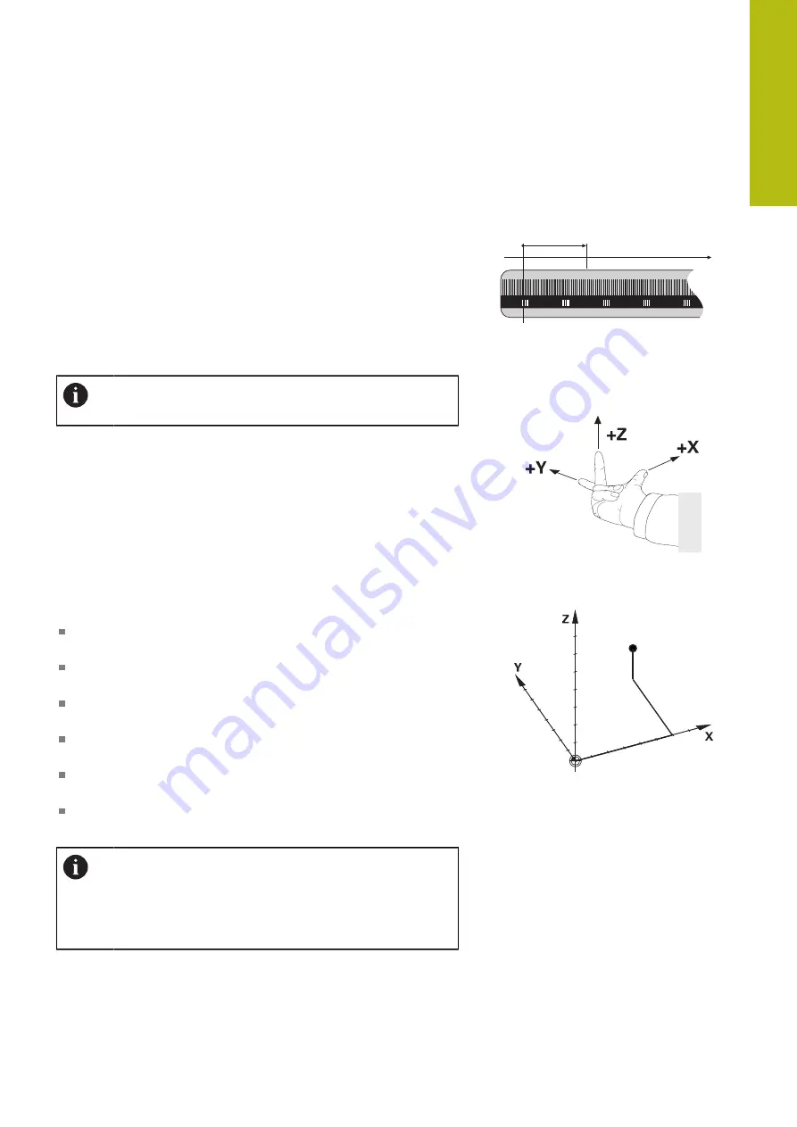
A paraxially mounted linear encoder on a machine tool serves
as a simple reference system for linear axes. The linear encoder
represents a
number ray
, a unidimensional coordinate system.
To approach a point on the
plane
, the control requires two axes and
therefore a reference system with two dimensions.
To approach a point in the
space
, the control requires three axes
and therefore a reference system with three dimensions. If these
three axes are configured perpendicular to each other this creates a
so-called
three-dimensional Cartesian coordinate system
.
According to the right-hand rule the fingertips point in
the positive directions of the three main axes.
For a point to be uniquely determined in space, a
coordinate origin
is needed in addition to the configuration of the three dimensions.
The common intersection serves as the coordinate origin in a 3-D
coordinate system. This intersection has the coordinates
X+0
,
Y+0
and
Z+0
.
The control must differentiate between various reference systems
for it to always perform a tool change at the same position for
example, or carry out a machining operation always related to the
current workpiece position.
The control differentiates between the following reference
systems:
Machine coordinate system M-CS:
M
achine
C
oordinate
S
ystem
Basic coordinate system B-CS:
B
asic
C
oordinate
S
ystem
Workpiece coordinate system W-CS:
W
orkpiece
C
oordinate
S
ystem
Working plane coordinate system WPL-CS:
W
orking
Pl
ane
C
oordinate
S
ystem
Input coordinate system I-CS:
I
nput
C
oordinate
S
ystem
Tool coordinate system T-CS:
T
ool
C
oordinate
S
ystem
All reference systems build up on each other. They are
subject to the kinematic chain of the specific machine
tool.
The machine coordinate system is the reference
system.
X
∆
Summary of Contents for TNC 640
Page 4: ......
Page 5: ...Fundamentals ...
Page 36: ...Contents 36 HEIDENHAIN TNC 640 Conversational Programming User s Manual 10 2017 ...
Page 67: ...1 First Steps with the TNC 640 ...
Page 90: ......
Page 91: ...2 Introduction ...
Page 130: ......
Page 131: ...3 Operating the Touchscreen ...
Page 144: ......
Page 145: ...4 Fundamentals File Management ...
Page 206: ......
Page 207: ...5 Programming Aids ...
Page 236: ......
Page 237: ...6 Tools ...
Page 281: ...7 Programming Contours ...
Page 333: ...8 Data Transfer from CAD Files ...
Page 355: ...9 Subprograms and Program Section Repeats ...
Page 374: ......
Page 375: ...10 Programming Q Parameters ...
Page 478: ......
Page 479: ...11 Miscellaneous Functions ...
Page 501: ...12 Special Functions ...
Page 584: ......
Page 585: ...13 Multiple Axis Machining ...
Page 650: ......
Page 651: ...14 Pallet Management ...
Page 664: ......
Page 665: ...15 Batch Process Manager ...
Page 673: ...16 Turning ...
Page 713: ...17 Manual Operation and Setup ...
Page 797: ...18 Positioning with Manual Data Input ...
Page 803: ...19 Test Run and Program Run ...
Page 843: ...20 MOD Functions ...
Page 881: ...21 Tables and Overviews ...