


Testing and running | Running CAM programs
6.11 Running CAM programs
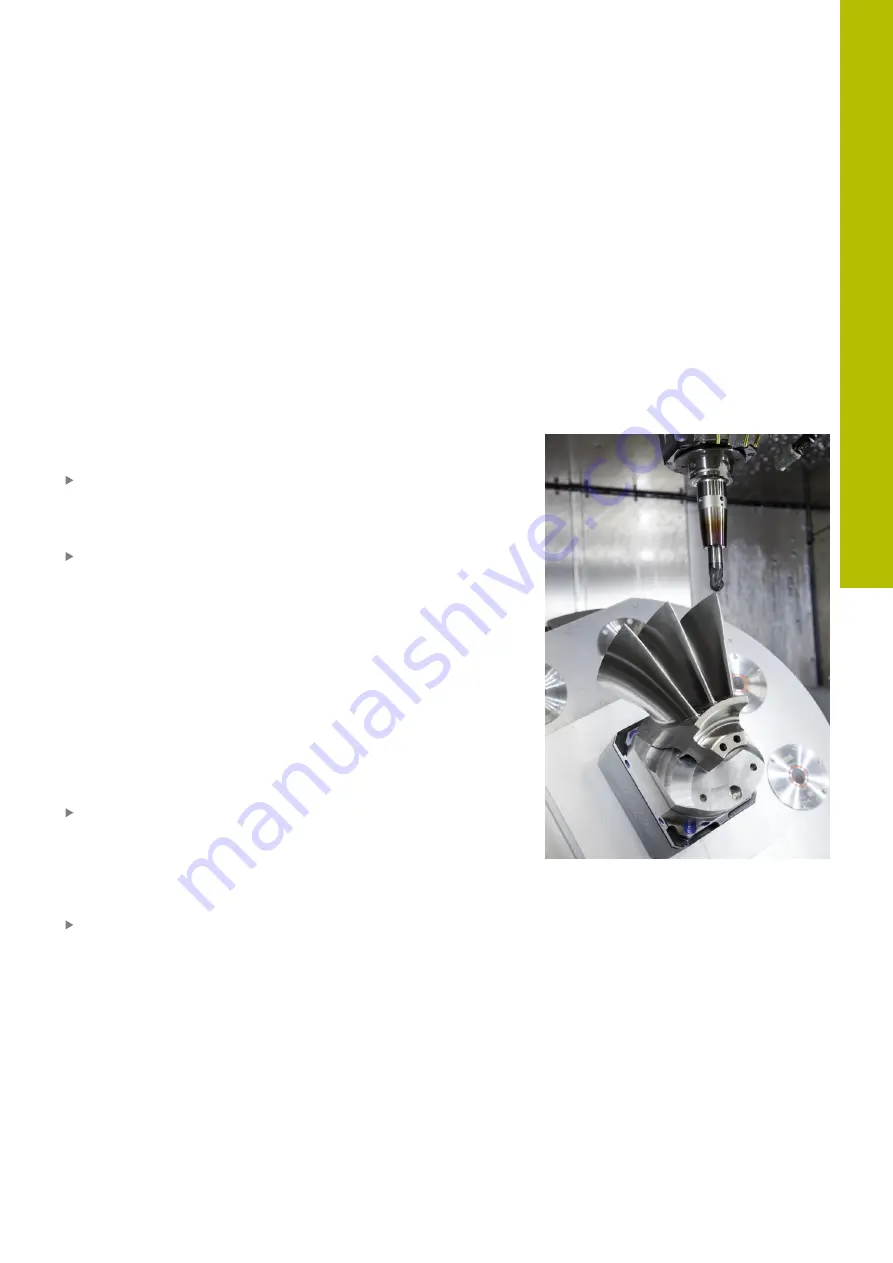
If you create NC programs externally using a CAM system, you
should pay attention to the recommendations detailed below.
This will enable you to optimally use the powerful motion control
functionality provided by the control and usually create better
workpiece surfaces with shorter machining times. Despite high
machining speeds, the control still achieves a very high contour
accuracy. The basis for this is the HEROS 5 real-time operating
system in conjunction with the
ADP
(Advanced Dynamic Prediction)
function of the TNC 620. This enables the control to also efficiently
process NC programs with high point densities.
From 3-D model to NC program
Here is a simplified description of the process for creating an NC
program from a CAD model:
CAD: Model creation
Construction departments prepare a 3-D model of the workpiece
to be machined. Ideally the 3-D model is designed for the center
of tolerance.
CAM: Path generation, tool compensation
The CAM programmer specifies the machining strategies for
the areas of the workpiece to be machined. The CAM system
uses the surfaces of the CAD model to calculate the paths of
the tool movements. These tool paths consist of individual
points calculated by the CAM system so that each surface
to be machined is approximated as nearly as possible while
considering chord errors and tolerances. This way, a machine-
neutral NC program is created, known as a CLDATA file (cutter
location data). A postprocessor generates a machine- and
control-specific NC program, which can be processed by the CNC
control. The postprocessor is adapted according to the machine
tool and the control. The postprocessor is the link between the
CAM system and the CNC control.
Control: Motion control, tolerance monitoring, velocity profile
The control uses the points defined in the NC program to
calculate the movements of each machine axis as well as the
required velocity profiles. Powerful filter functions then process
and smooth the contour so that the control does not exceed the
maximum permissible path deviation.
Mechatronics: Feed control, drive technology, machine tool
The motions and velocity profiles calculated by the control
are realized as actual tool movements by the machine’s drive
system.
6
HEIDENHAIN | TNC 620 | User's Manual for Setup, Testing and Running NC Programs | 01/2022
291
Summary of Contents for TNC 620
Page 4: ...Contents 4 HEIDENHAIN TNC 620 User s Manual for Setup Testing and Running NC Programs 01 2022...
Page 6: ...Contents 6 HEIDENHAIN TNC 620 User s Manual for Setup Testing and Running NC Programs 01 2022...
Page 24: ......
Page 25: ...1 Basic information...
Page 43: ...2 First steps...
Page 55: ...3 Fundamentals...
Page 126: ......
Page 127: ...4 Tools...
Page 165: ...5 Setup...
Page 245: ...6 Testing and running...
Page 311: ...7 Special functions...
Page 316: ......
Page 317: ...8 Pallets...
Page 339: ...9 MOD functions...
Page 368: ......
Page 369: ...10 HEROS functions...
Page 470: ......
Page 471: ...11 Operating the touchscreen...
Page 488: ......
Page 489: ...12 Tables and overviews...


