HEIDELBERG PG.010.000B User Manual Download Page 17

Before you start ...

Suprasetter 145/162/190 – User’s Guide

17

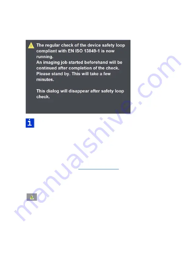
Note: During the check of the safety loop, it is not possible to image 
plates.

The window closes automatically as soon as the check is finished (this can take 
some minutes).

Manual check of the safety loop

The user can run an early check of the safety loop at any time before the 24-
hour time limit expires (see 

"Timeframe", page 18

) if, for example, a suitable 

moment in production allows this.

Start check of safety loop

The check of the safety loop starts after you click this button in the 
user interface and confirm again.

Summary of Contents for PG.010.000B

Page 1: ...Suprasetter 145 162 190 User s Guide 08 2019 Order No PG 999 0005...

Page 2: ...egulations regarding the protection of trade marks Important notice We are dedicated to improving and enhancing our products Conse quently the information in this manual is subject to change without n...

Page 3: ...eneral 10 Power Switch with Emergency Cutoff Function 13 Emergency Stop Switch 13 On Off button 13 Laser Safety 14 Service and Maintenance 15 Safety Loop 16 Check of the safety loop 16 Automatic check...

Page 4: ...tallation Container Version 30 Saving a Backup of the Recorder Configuration 31 Selecting the User Interface Language 32 Operation Power on and Power off Rules with a Linux Operating System 33 Power o...

Page 5: ...by the User 54 Cleaning the Suprasetter 55 Cleaning the Cleaning Roller on a manual Suprasetter and on a Semi automatic Device 55 Cleaning the Cleaning Roller on a Fully Automated Device with a Cross...

Page 6: ...n and Safety Requirements 95 Standards 95 General safety 95 Laser Safety 95 Mechanical Safety 96 Electrical safety 96 Electromagnetic Compatibility EMC 96 Interference emission stray radiation and int...

Page 7: ...se should be familiar with the Supra setter Symbols and Styles The following typographical conventions are used in this manual References to other chapters and sections are blue on the screen and unde...

Page 8: ...a hazard with a high risk which if not avoided will result in death or severe injury Warning The WARNING signal word indicates a hazard with a medium risk which if not avoided can result in death or...

Page 9: ...e Names Intended use The Suprasetter is a laser imagesetter for imaging offset printing plates and may only be used for this purpose as described in the customer documenta tion All other use that does...

Page 10: ...the Suprasetter is located are adhered to The air exchange must be arranged in such a way that the measured dust particles are regularly below the exposure limit values In accordance with the state of...

Page 11: ...ar protective gloves Caution Risk of injury from improper handling The following loads should not be exceeded women 15 kg men 25 kg Warning Risk of injury if safety system bypassed The key operated sw...

Page 12: ...rom improper handling You run the risk of injuring yourself between the insertion ejection table and the cross conveyor of the Suprasetter when printing plates with sharp edges are output You can inju...

Page 13: ...upply by the power switch red rotary switch The power switch red rotary switch triggers an all pole cut off of the Supra setter from the power supply In an emergency it is to be used as an emergency c...

Page 14: ...aser systems used in the Suprasetter are Class 4 products 500 mW Companies servicing the equipment in Germany must appoint a laser protec tion officer in compliance with the Accident Prevention Regula...

Page 15: ...s If you do not the invisible laser beam may cause injuries to eyes and skin and or you may suffer a fatal electric shock Warning Risk of injury from laser radiation You may be exposed to dangerous ra...

Page 16: ...check of the safety loop This regular check is triggered automatically after the following criteria When switching on the Suprasetters When running certain error corrections When the machine is runni...

Page 17: ...is finished this can take some minutes Manual check of the safety loop The user can run an early check of the safety loop at any time before the 24 hour time limit expires see Timeframe page 18 if fo...

Page 18: ...will help reduce the frequency and intensity of the discharges Formation In a prepress environment this physical phenomenon occurs most frequently as a result of triboelectricity In such cases electro...

Page 19: ...N 61340 5 Synthetic carpet ing does not comply with this requirement in the majority of cases Pure concrete flooring generally has a low volume resistance If you have non conductive floor covering the...

Page 20: ...he following sources IEC EN 61340 5 Protection of electronic devices from electrostatic phenomena General Requirements Electrostatic Discharge Association http www esda org Electrostatic Society of Am...

Page 21: ...Suprasetter 145 162 190 User s Guide 21 Heidelberg online Do you have questions concerning our products Do you want to improve your workflows Then visit us on the Internet You can find us at http www...

Page 22: ......

Page 23: ...e cassette magazine The Suprasetter automatically loads the plate onto the drum images it punches it option and conveys the imaged plate back to the insertion table or to the connected ejection table...

Page 24: ...r are indicated by the status LEDs Status LED Action Left half Right half Startup The Suprasetter starts the software and ini tializes the hardware The status LEDS are like level indicators fill ing u...

Page 25: ...s flash synchronously Error An error occurred that must be eliminated by the user The LEDs on each level flash alternating between left and right A beep also indicates the error status The user must g...

Page 26: ...page 34 switch off the Suprasetter see section Switching off the Suprasetter page 36 switch off the beep that sounds for example after a malfunction occurs Waiting for a plate The user is prompted to...

Page 27: ...y be used in the Suprasetter Similarly only slip sheets that are also qualified and approved may be used in the Suprasetter The use of unapproved plates and slip sheets can result in malfunctions in t...

Page 28: ......

Page 29: ...Because the installation site must have clean conditions the Suprasetter may not be operated in sites where paper is being printed or paper finish ing devices are running The floor at the installation...

Page 30: ...rder configuration is saved see the section Saving a Backup of the Recorder Configuration page 41 A buffer plate named Pagebuff is available and formatted Operation 1 Insert the Suprasetter installati...

Page 31: ...ion is complete 12 To start the Suprasetter user interface select Start Programs Heidel berg CTP User Interface or use the previously set path 13 Switch the Suprasetter on Saving a Backup of the Recor...

Page 32: ...e User Interface Language 1 Click the Change to Device button 2 Select Options in the vertical menu bar 3 Select the Miscellaneous tab 4 Select the language you want in Language 5 Click Apply The user...

Page 33: ...ved unforeseeable errors and issues may occur in the com munication between the devices that can be remedied only by a power on and power off of the Suprasetter in the correct order as described below...

Page 34: ...ff state when you restart the workstation PC Workstation PC restart The Suprasetter must be in an off state when you restart the workstation PC Switching on the Suprasetter Manual Startup Prerequisite...

Page 35: ...ure at the installation site to reach its operating temperature For that reason it has an automatic startup mechanism that can be used to switch on the device at defined periods for example a half an...

Page 36: ...u can also set the startup day in addition to the start time in Schedule Once 7 Click Apply The startup time is saved and the Suprasetter will switch itself on at this time Switching off the Suprasett...

Page 37: ...vicing 4 Switch off the workstation PC Shutdown with the On Off button on the Supraset ter 1 Press and hold down the On Off button approx 3 seconds until you hear a beep Notice At all times keep to th...

Page 38: ...ond time before you have done step 3 4 Set the power switch to 0 on the Suprasetter for cleaning and servicing 5 Switch off the workstation PC Fig 2 Switch off power switch Note The workstation PC mus...

Page 39: ...shutdown sequence again 1 Press and hold down the On Off button approx 3 seconds until you hear a beep 2 Release the On Off button 3 Press the On Off button a second time Now repeat shutdown 4 Press a...

Page 40: ...ip sheets when you place printing plates on top of each other so that they cannot scrape against each other Do not load plates that are obviously damaged to the Suprasetter This can cause malfunctions...

Page 41: ...d a printing plate to the device if the lower part of the two status LEDs is flashing and the load buttons are lit The inser tion rollers first open for you to load a printing plate This is accompa ni...

Page 42: ...n Risk of injury from improper handling Plate edges can be sharp Put on protective gloves This will protect you from injury Notice Never handle printing plates on your own Two persons are always requi...

Page 43: ...uprasetter as far as the mechanical stop 7 Press one of the two load buttons The plate is loaded to the Suprasetter This is accompanied by a brief beep Note If you do not press the load button the pla...

Page 44: ...plate after it is inserted The plate is immediately transported back to the insertion table if the wrong length was detected Three beeps are heard and the load buttons flash You must remove the plate...

Page 45: ...e is output you will hear a brief beep again indicating that the plate can now be removed 1 Put on protective gloves 2 Remove the printing plate from the Suprasetter for further processing Caution Ris...

Page 46: ...Operation 46 Version 2019 Fig 6 Removing a Printing Plate...

Page 47: ...ions to eliminate the error 2 Click the Correct error button This action returns the Suprasetter to its initial status and the function which was interrupted by the error can be repeated Notice If you...

Page 48: ...panel Notice The loader turns red in the 3D display if an error occurs in the loader If imaging is also running parallel to that you can run an error correction only after imaging is finished and the...

Page 49: ...Operation Suprasetter 145 162 190 User s Guide 49 Fig 13 Remove side panel 2 Switch on the automatic cutout that was triggered Side panel...

Page 50: ...rsion 2019 Fig 14 Automatic Cutouts 3 Please inform your maintenance service if you cannot switch on an auto matic cutout again so that this malfunction can be remedied 4 Put the side panel back on Au...

Page 51: ...Operation Suprasetter 145 162 190 User s Guide 51 Fig 15 Insert side panel Side panel...

Page 52: ......

Page 53: ...57 Removing Punch Waste on a manual Suprasetter and on a Semi automatic Device page 60 Removing Punch Waste on a Fully Automated Device with a Cross Conveyor or OLP Table page 62 and Changing the Fil...

Page 54: ...e Users After installation users will be instructed in the operation and service and maintenance of the Suprasetter by Heidelberg service personnel Further instruction for example for new staff employ...

Page 55: ...ning Roller on a manual Supraset ter and on a Semi automatic Device A message prompts the user to clean the cleaning rollers Cleaning cycle 500 printing plates Cleaning agents Water sponge sponge clot...

Page 56: ...r is set to an error state after you click the Cleaning Roller button 2 Open the cover on the front of the device Fig 1 Open cover 3 Clean the cleaning roller using a sponge or sponge cloth moistened...

Page 57: ...column The number of plates in the Next Maintenance column is reset to its initial value 7 Click Apply and confirm the query with Yes The maintenance interval for cleaning the cleaning roller starts...

Page 58: ...2 Unlock the wheels of the cross conveyor 3 Push the cross conveyor approx 70 cm away from the Suprasetter to be able to reach the cleaning roller Note If you use an OLP table instead of a cross conv...

Page 59: ...cover of the insertion ejection table By pushing the cross conveyor you can lift the protective cover so that it lies on the side parts of the cross con veyor A second person can also help you lift th...

Page 60: ...ing roller starts from the begin ning 11 Run a troubleshooting routine to eliminate the error state of the Supra setter see the section Troubleshooting page 47 Removing Punch Waste on a manual Suprase...

Page 61: ...Service and Maintenance Suprasetter 145 162 190 User s Guide 61 Fig 4 Open cover 3 Remove the punch waste containers from the device and empty them Fig 5 Punch waste containers 1...

Page 62: ...Apply and confirm the query with Yes The maintenance interval for removing the punch waste starts from the begin ning 8 Run a troubleshooting routine to eliminate the error state of the recorder see t...

Page 63: ...r Note If you use an OLP table instead of a cross conveyor you must first manually swing up the protective cover on the insertion ejection table in order to swing up the OLP table After that the OLP t...

Page 64: ...es you no longer need at your local waste disposal company 6 Place the punch waste containers back on the guides Push them to the back as far as they can go so that the punch waste is sure to fall int...

Page 65: ...must be lowered again if this is used instead of a cross conveyor 9 In the Suprasetter user interface go to Administration Maintenance Monitoring and click the box in the Punch Waste row in the Maint...

Page 66: ...to request this information if you do not have it Note After you remove the filters clean the casing with a vacuum cleaner Place the used filters disposable gloves dust mask and vac uum cleaner bag i...

Page 67: ...changing you notice that one of the filter kits is heavily soiled or both filter kits are still clean The maintenance interval can then be changed accordingly 1 Remove the right hand side panel Fig 8...

Page 68: ...of the dirty filters and the light dust mask Loosen the six rocker arm locks and move the casing cover to the side Fig 9 Loosen rocker arm locks 3 Remove the high efficiency submicron particulate air...

Page 69: ...ver above the preliminary filter 6 Place the preliminary filter in the plastic bag as well 7 Clean the filter casing with a vacuum cleaner 8 Place the vacuum cleaner bag dust mask and disposable glove...

Page 70: ...s and tighten the cover with the wing nuts 14 Put the casing cover back into place Make sure that the casing cover is seated properly on the rubber seal 15 Close the rocker arm locks 16 Put the side p...

Page 71: ...ances It must be handed over to an approved waste disposal company and not be disposed of as household waste Addresses can be obtained from the relevant environmental offices The details of this dispo...

Page 72: ...th depth height 3400 mm x 1836 mm x 1560 mm Weight of the device 1600 kg Harmful substances The table below lists the parts that contain harmful substances and therefore must be disposed of or recycle...

Page 73: ...il Productinformation Performance Chemicals basf ag de Description Harmful Substances Image No Pos Various pcbs Tetrabrombisphenol A etc 2 1 Power supply modules Tetrabrombisphenol A etc 2 3 Pilot lam...

Page 74: ...rial Weight approx kg Image No Pos 1 Cover plates Aluminum ENAW AlMg3 powder coated 150 8 1 2 Table top Aluminum ENAW AlMg3 powder coated 25 9 1 2 3 Base plates Sheet steel galva nized 60 8 3 4 Base f...

Page 75: ...10 7 13 Various parts mounting parts motors pumps cables rubberized rollers Steel aluminum plastic cast alumi num copper 400 Pos Description Material Image 8 1 Dismantle the sheet metal cover ings Hin...

Page 76: ...t lowest point Disposal of the coolant must be environmentally safe following the manufacturer s instructions The notes on job safety in the safety data sheet must be observed Image 4 2 Dismantling of...

Page 77: ...Disposal Suprasetter 145 162 190 User s Guide 77 Fig 2 Recorder disposal 1 3 Various PCBs and power supply modules 2 Distributor PCB 3 2 3 1...

Page 78: ...Disposal 78 Version 2019 Fig 3 Recorder disposal 1 PCBs in punches 2 Distributor PCB 2 1...

Page 79: ...Disposal Suprasetter 145 162 190 User s Guide 79 Fig 4 Recorder disposal 1 3 4 Interface PCBs 2 Laser module 4 3 2 1...

Page 80: ...Disposal 80 Version 2019 Fig 5 Recorder disposal 1 Light barrier pcb 1...

Page 81: ...Disposal Suprasetter 145 162 190 User s Guide 81 Fig 6 Recorder disposal 1 Filters in suction device 1...

Page 82: ...Disposal 82 Version 2019 Fig 7 Disposal of the recorder 6 1 Pilot lamps 1...

Page 83: ...Disposal Suprasetter 145 162 190 User s Guide 83 Fig 8 Recorder disposal 1 Cover plates 2 Base frame 3 Base plates 2 1 3...

Page 84: ...Disposal 84 Version 2019 Fig 9 Recorder disposal 1 2 Table top 2 1...

Page 85: ...Disposal Suprasetter 145 162 190 User s Guide 85 Fig 10 Recorder disposal 1 Punch bar 2 VCT bar 3 Side panels 2 off 4 Imaging drum 5 Machine base 6 Imaging rails 3 2 3 1 4 5 7 6...

Page 86: ...ader Size of the device width depth height 3400 mm x 1255 mm x 1560 mm Weight of the device 800 kg Harmful substances The table below lists the parts that contain harmful substances and therefore must...

Page 87: ...tinformation Performance Chemicals basf ag de Recyclable Materials The following table lists the main parts that do not contain harmful substances and that can undergo environmentally safe recycling T...

Page 88: ...er coated 100 12 4 2 Base plates Sheet steel galva nized 36 12 6 3 Base frame Aluminum AlMg SiO 5F25 130 12 7 4 Tables Aluminum plate EN AW AlMg3 pro file AlMgSiO 5F25 125 12 5 5 Carriers 2x Aluminum...

Page 89: ...es and hoses 3 Remove electronic components assemblies and motors Dispose of professionally as elec tronic waste 4 Dismantle the chiller and dispose of it professionally see disposal instructions belo...

Page 90: ...lates 7 Base frame 8 Beams aluminum Disposal instructions for the Termotek chiller printed with the permission of Termotek AG The chiller comprises several components that must be disposed of separate...

Page 91: ...parts etc can be disposed of as household waste or at recycling centers The entire cooling circuit must be disposed of by a company certified according to 52 para 1 of the Closed Substance Cycle Waste...

Page 92: ......

Page 93: ...2600 kg Power supply 400 V three phase connection Y con nection N PE Frequency 50 60 Hz Rated operational current 3 x 15 A three phase connection Power consumption 10 kW Heat Radiation 36000 KJ h 340...

Page 94: ...060 mbar Noise emission 70 dB A workplace related value Plate sizes Suprasetter 145 Min 500 mm x 650 mm Max 1425 mm x 1460 mm Suprasetter 162 Min 500 mm x 650 mm Max 1425 mmx 1630 mm Suprasetter 190 M...

Page 95: ...es listed below General safety 2 Laser Safety Please refer to the label overview at the end of this chapter for laser labels and their positions 3 ProdSG Product Safety Act 2011 Germany 2006 42 EC Mac...

Page 96: ...0 Europe EN 1010 1 2 Europe IEC 68 2 6 International IEC 68 2 7 International EN ISO 13849 1 International EN 60204 1 Europe IEC 60204 1 International EN 60950 1 Europe IEC 60950 1 International UL 60...

Page 97: ...e compliance with the radio interference suppression regulations when you connect other electrical equipment to this unit by following the instructions given by the manufacturer of this equipment rega...

Page 98: ...vicing are followed Approvals and conformity 9 CE Declaration of Conformity The circumstances listed below are valid solely within the member states of the European Union EU You received a copy of the...

Page 99: ...Technical Data Suprasetter 145 162 190 User s Guide 99 Labels on the Suprasetter 145 162 190 Type label recorder Basic principle...

Page 100: ...Technical Data 100 Version 2019 I O table type label CE mark of conformity Laser Product Class 1...

Page 101: ...Technical Data Suprasetter 145 162 190 User s Guide 101 Caution Class 4 laser radiation Installation instructions Note on conformance...

Page 102: ...Technical Data 102 Version 2019 Beware of moving parts Electric shock hazard Data cable connection warning High leakage current...

Page 103: ...Technical Data Suprasetter 145 162 190 User s Guide 103 Air Inlet Air Outlet AC outlet...

Page 104: ...Technical Data 104 Version 2019 Warning information labels on suction unit Power switch identification...

Page 105: ...Technical Data Suprasetter 145 162 190 User s Guide 105 Power switch with identification label...

Page 106: ...Technical Data 106 Version 2019 Recorder with plate loader 1 Type label recorder 2 Laser Product Class 1 3 Note on conformance 4 Type label recorder 5 CE mark of conformity 1 5 4 3 2...

Page 107: ...Technical Data Suprasetter 145 162 190 User s Guide 107 Recorder power connection and fuses 1 Electric shock hazard 1...

Page 108: ...Technical Data 108 Version 2019 Recorder power supply box outside 1 Air Inlet 2 High leakage current 3 Installation instructions 4 Electric shock hazard 1 4 3 2...

Page 109: ...Technical Data Suprasetter 145 162 190 User s Guide 109 Recorder compressed air 1 AC outlet connector socket for cross table 2 Air Outlet compressed air connection for the Autoloader 1 2...

Page 110: ...Technical Data 110 Version 2019 Recorder right side 1 Beware of moving parts 2 Caution Class 4 laser radiation 3 Warning information labels on suction unit 3 2 1...

Page 111: ...Technical Data Suprasetter 145 162 190 User s Guide 111 Recorder left side 1 Beware of moving parts 2 Caution Class 4 laser radiation 3 Electric shock hazard 1 3 2...

Page 112: ...Technical Data 112 Version 2019 Recorder cross beam in front of exposure drum 1 Beware of moving parts 2 Caution Class 4 laser radiation 1 2...

Page 113: ...Technical Data Suprasetter 145 162 190 User s Guide 113 Recorder lifting table of plate loader 1 Beware of moving parts on both sides of the upper side rail 1...

Page 114: ...Technical Data 114 Version 2019 Recorder electronics unit 1 Data cable connection warning 2 Electric shock hazard 1 2...

Page 115: ......

Page 116: ...ger Druckmaschinen AG Kurfuersten Anlage 52 60 69115 Heidelberg Germany Phone 49 62 21 92 00 Fax 49 62 21 92 69 99 www heidelberg com For further information please contact your local Heidelberg repre...

Reviews: