background image

9

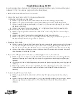
Troubleshooting S1505

In order to make these checks an AC Voltmeter is required. Both the control circuit and the motor
voltage is 115VAC. Use extreme caution when checking voltage.

1. Push start button and hold for 2 to 3 seconds.

2. Motor relay and control relay #1 to close simultaneously

1) If motor relay does not close check:

a) If there is power between the coil terminals of the motor starting relay is faulty.
b) If there is no power between these two terminals then proceed to check delay timer.
c) If there is power between terminals 1 & 2 and 2 & 3, but no power between 2 & 6, then 

the timer is defective.

d) If there is no power between terminals 2 & 3, of the timer then check the start switch.

2) If control relay #1 does not close then check:

a) If there is power present at terminals A & B of the control relay then the control relay is 

defective.

b) If there is no power between these terminals then check the stop switch.
c) If there is power on the common (middle) terminal of the stop switch but no power on 

the NC terminal then the stop switch is defective.

3. Fan starts, if not check:

a) If there is power between the black and white wires inside the motor junction box (located

on side of motor) then the motor may need manual resetting. Pushing the red button on 
the side of the junction box. If this does not correct the problem then the motor is faulty.

b) If there is no power at these two wire ends then check the motor relay contacts, they may 

need cleaning or replacing, if burnt.

4. Fan reaches full speed, airswitch closes, and white light comes on, if not check:

a) If there is power on only one of the airswitch terminals while motor is running, then the 

airswitch is staying open. First check if either the upstream or down stream airtubes are 
plugged.

b) If both are free then check alignment (tubes must be positioned parallel to the direction of

airflow)

c) If above procedures do not correct problem, then the adjusting screw located on the side 

of the airswitch can be rotated counter clockwise, just enough so that the fan stays 
running.

5. Control relay #2 closes, if not check:

a) If there is power between terminals A & B of relay #2, if power is present then relay is 

faulty

b) If there is power between terminals L1 & L2 of the Fenwall module, but no power 2 sends 

after start-up between terminals V1 & V2 of the Fenwall, then the Fenwall module is 
defective.

Summary of Contents for S1505

Page 1: ...lease retain this manual for future reference 342 N Co Rd 400 East Valparaiso IN 46383 219 464 8818 Fax 219 462 7985 www heatwagon com Revision 9 13 For your safety Do not use this heater in a space where gasoline or other liquids having flammable vapors are stored ...

Page 2: ...use which may be made for our heaters CHECK WITH YOUR LOCAL FIRE SAFETY AUTHORITY IF YOU HAVE QUESTIONS ABOUT LOCAL REGULATIONS Other standards govern the use of fuel gases and heat producing products in specific applica tions Your local authority can advise you about these FOR YOUR SAFETY DO NOT USE THIS HEATER IN A SPACE WHERE GASOLINE OR OTHER LIQ UIDS HAVING FLAMMABLE VAPORS ARE STORED OR USED...

Page 3: ...ies will not be considered Warranty claims must include model number and serial number LIMITATIONS Warrant claims for service parts wear parts such as spark plugs igniters flame rods will not be allowed Diagnostic parts such as voltage meters and pressure gauges are not warrantable Evidence of improper fuel usage fuel pressures outside of manufacturer s specification poor fuel quality and improper...

Page 4: ...FETY FEATURES 1 Locking position for LPG on gas selector lever Units used with LPG while the gas selector valve is positioned for Natural Gas will throw significantly more heat than the rated Btu h This is definitely a safety hazard 2 Low skin temperature Sure Flame Heaters are designed to have a low skin temperature This provides added safety in the workplace 3 Durable Construction The Model S150...

Page 5: ...nsure that the pressure at the heater inlet is within specified range Please refer to Propane and Natural Gas installation sections on Page 7 Excessive pressure over 1 2 psig will damage the controls and void the warranty 3 Visually inspect the hose assembly and ensure that it is protected from traffic building materials and contact with hot surfaces If it is evident that there is excessive abrasi...

Page 6: ...en installing the heater for use with Natural Gas set the selector valve to the Natural position 2 A regulator must be installed on the heater only if the line pressure to the heater is greater than 1 2 psi 3 The installation of this heater to a natural gas supply must conform with all applicable local codes or in the absence of local codes with the National Fuel Gas Code ANSI Z223 1 NFPA 54 Opera...

Page 7: ...n a dirty environment 7 Improper Supply of Fresh Air It is normally recommended that the intake air of the heater be taken from outside the enclosed area This provides a slight pressurization and prevents any problems associated with recirculation On Site Safety Problems 1 Shorting out of defective components This is a very common problem which saves short term expense at the risk of a large futur...

Page 8: ...d To maintain reli able performance required it is necessary to do a certain amount of regular maintenance A Visual Checks The following items should be checked for excessive wear or damage 1 Wheels 2 Cords and Connectors 3 Wiring and Conduit 4 Heater shell including heat shield and Control Box B Burner Flame rod and insulator Clean with soap and water or solvent on a routine basis Any build up on...

Page 9: ... check a If there is power between the black and white wires inside the motor junction box located on side of motor then the motor may need manual resetting Pushing the red button on the side of the junction box If this does not correct the problem then the motor is faulty b If there is no power at these two wire ends then check the motor relay contacts they may need cleaning or replacing if burnt...

Page 10: ... no power at terminal V1 of the Fenwall then the Fenwall module is faulty 7 Flame rod senses and maintains flame if not check a If flame rod wire is connected to flame rod and not grounding out to the heater b If flame rod wire is inserted into the correct location on the Fenwall module c The flame rod must always be screwed into the burner securely The probe part should not be touching the burner...

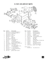
Page 11: ...age Regulator Valve 16 SFP 2537 1 5 Solenoid Valve 17 SFP S1505 81 1 5 Gas Selector Valve 18 SFP 2539 1 5 Manual Shut Off valve 19 SFP SL11B 58 Control Box 20 SFP 7462 Ignition Control Module Item Part No Description 21 SFP 5768 Terminal Block 3 22 SFP 2436 Motor Starting Relay 23 SFP 3337G ON Switch Green 24 SFP 5989 Voltmeter 25 SFP 3337R OFF Switch Red 26 HWP HC1002 Circuit Breaker for item 20 ...

Page 12: ...12 ...

Page 13: ...13 ...

Page 14: ...14 ...

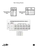
Page 15: ...3 4 50 2 1 1 4 1 1 4 3 4 75 2 1 2 1 1 2 1 1 4 3 4 100 2 1 2 1 1 2 1 1 4 1 1 4 125 2 1 2 1 1 2 1 1 4 1 1 4 150 2 1 2 2 1 1 4 1 1 4 VAPOR PROPANE QUICK REFERENCE HOSE CHART Hose BTU Length 1 5 Million in Feet 1 2PSI 10PSI 10 1 1 4 3 4 25 1 1 4 3 4 35 1 1 4 3 4 50 1 1 4 3 4 75 3 4 100 3 4 125 3 4 150 1 1 4 175 1 1 4 200 1 1 4 225 1 1 4 Fuel Sizing Charts ...

Page 16: ......

Reviews: