059700-00 Rev. B
INSTALLATION AND
OPERATION MANUAL
2-WAY AND 3-WAY
MOTORIZED VALVES
FOR STEAM, VACUUM, AND HOT WATER
Page 1: ...059700 00 Rev B INSTALLATION AND OPERATION MANUAL 2 WAY AND 3 WAY MOTORIZED VALVES FOR STEAM VACUUM AND HOT WATER...
Page 2: ...used as a primary limit or safety control All equipment must have its own certified limit and safety controls required by local codes The installer must verify proper operation and correct any safety...
Page 3: ...Y SINGLE SEATED VALVES 11 04 INSTALLATION INSTRUCTIONS 12 SUPPLIED MATERIALS 12 REQUIRED MATERIALS NOT SUPPLIED 12 DESIGN CONSIDERATIONS 13 CALCULATING VALVE SIZING 14 HOT WATER VALVE SIZING 14 STEAM...
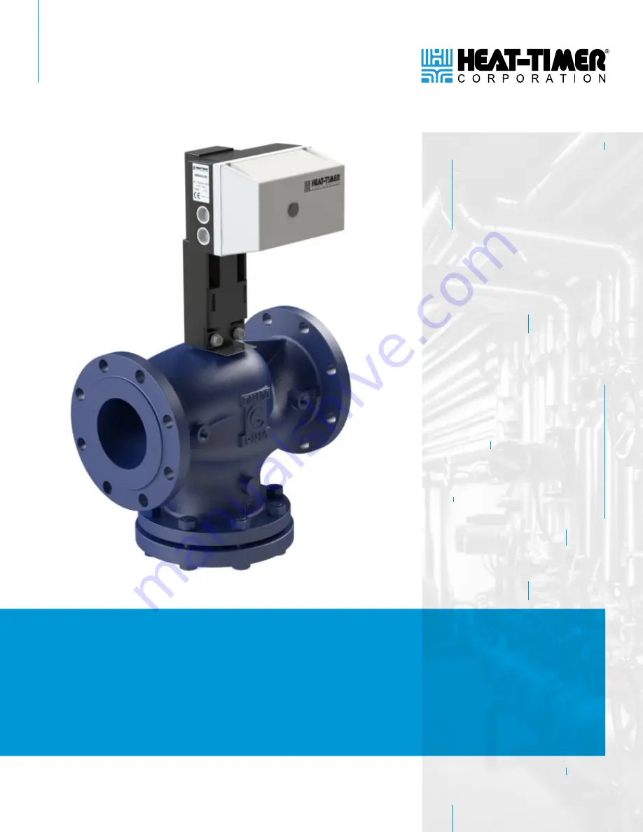
Page 4: ...EM DESCRIPTION 1 Valve Body 2 Valve Actuator 3 Wiring Entry Fittings 4 Actuator Manual Adjustment Knob 5 Wiring Connections Terminal Y1 Drives Valve Stem Up Terminal N 24Vac Common Terminal Y2 Drives...
Page 5: ...minal Y1 Drives Valve Stem Up Terminal N 24Vac Common Terminal Y2 Drives Valve Stem Down Terminal W1 Valve OPEN Signal Terminal W2 Common Terminal W3 Valve CLOSE Signal 01 CONTROLS INDICATORS AND CONN...
Page 6: ...uator Manual Adjustment Knob 6 Wiring Connections Terminal L1 24Vac Connection Terminal L2 24Vac Connection Terminal M Common Terminal V 15V Output Terminal Y 0 10V Control Signal Input Terminal S1 Fe...
Page 7: ...the flow of sub atmospheric steam from the boiler or other source into a steam distribution system Actuators are equipped with a position feedback signal A typical example of this type of application...
Page 8: ...damage to the equipment Only manually operate the valve when power has been removed from the actuator DO NOT attempt to force the manual control beyond the end of the actuator stroke 1 Ensure power h...
Page 9: ...c Floating Power Consumption 12VA Operating Temperature Ambient 5 F to 122 F 15 C to 50 C Locations NEMA Type 2 IP54 Indoor Only User Interface Manual Override Handle Status Valve Position Feedback Si...
Page 10: ...8 928078 XX Double Seated 578 23 6 10 8 23 4 400 2 NOTE Replace XX as follows 00 for 24V Floating Actuator CV for 0 10V Proportional Actuator VAC for 24V Floating Actuator with Valve Position Feedback...
Page 11: ...206 2 NOTE Replace XX as follows 00 for 24V Floating Actuator CV for 0 10V Proportional Actuator VAC for 24V Floating Actuator with Valve Position Feedback VALVE SPECIFICATIONS Valve Body Material AN...
Page 12: ...eplace XX as follows 00 for 24V Floating Actuator CV for 0 10V Proportional Actuator VAC for 24V Floating Actuator with Valve Position Feedback VALVE SPECIFICATIONS Valve Body Material ANSI B16 1 Iron...
Page 13: ...h the control module 24Vac 40VA Transformer p n 210006 00 Installation and Operation Manual p n 056700 00 Warranty Card p n 059115 00 REQUIRED MATERIALS NOT SUPPLIED The following materials tools are...
Page 14: ...l not cause damage to the surrounding area Consider the location of any new or existing piping and electrical components General piping guidelines All piping including the piping of the valve body mus...
Page 15: ...ection of a steam valve in a zoning situation should be based on minimizing the drop across a 2 way valve In the case of heat exchangers the objective is to allow maximum capacity flow as specified by...
Page 16: ...ion 3 If installing a single seat valve determine whether the installation requires a 2 way or 3 way configuration To use the valve in a 3 way configuration Remove the cover 1 from valve port B by rem...
Page 17: ...valve port B moving UP closes valve port A and opens valve port B All valve ports are marked with the letters A B and AB CAUTION For hot water applications ensure the pump is installed after the valve...
Page 18: ...ere space restrictions dictate the valve actuator assembly can be mounted in any position as long as the valve is not upside down or the actuator manual control knob is not facing up or down see Figur...
Page 19: ...uator to the valve by sliding the T Stem Nut 2 into the C Bracket 1 on the Actuator If necessary use the actuator Manual Adjustment Knob 3 to adjust the position of the U Bolt 8 until it is aligned wi...
Page 20: ...24Vac transformer s For configurations where a control device is operating two actuators in series a single transformer can be used to power both actuators If a control device is operating two actuat...
Page 21: ...or to a 3 way valve in the standard configuration port A cold port B hot see Figure 8 Page 24 a Connect the Control OPEN terminal to actuator terminal Y1 b Connect the Control CLOSE terminal to actuat...
Page 22: ...onnect the Control CLOSE terminal to actuator terminal Y2 If connecting to a 3 way valve in the alternate configuration port A hot port B cold see Figure 9 Page 24 a Connect the Control OPEN terminal...
Page 23: ...g from the Heat Timer Control terminals to the actuator terminals L1 and L2 If the control input signal to the actuator is not 0 10V the wiring remains the same as described in Step 4 and the selectio...
Page 24: ...rently at DIP SELECTION OF VALVE DIRECTION PROPORTIONAL ACTUATOR Reference the SW3 terminals in Figure 7 The actuator is currently defaulted to pull the valve stem up with a 10V signal or high input s...
Page 25: ...8 ACTUATOR WIRING DIAGRAM 2 WAY VALVE OR 3 WAY VALVE STANDARD CONFIGURATION HEAT TIMER CONTROL ACTUATOR 24Vac TRANSFORMER ACTUATOR WIRE TERMINAL CLOSE COMMON OPEN Y1 N Y2 120Vac HEAT TIMER CONTROL AC...
Page 26: ...B HEAT TIMER CORP 25 FIGURE 10 ACTUATOR WIRING DIAGRAM FLOATING ACTUATOR WITH FEEDBACK AND SRC PLATINUM FIGURE 11 ACTUATOR WIRING DIAGRAM PROPORTIONAL ACTUATOR AND DIGI SPAN MCA 0 10V 04 INSTALLATION...
Page 27: ...ater getting hotter when the valve closes Incorrect valve port used Ensure the valve was installed using the correct valve ports Refer to Table 1 on page 16 Difficult to control water temperature Pump...
Page 28: ...059700 00 REV B HEAT TIMER CORP 27 06 NOTES...
Page 29: ...28 HEAT TIMER CORP 059700 00 REV B 06 NOTES...
Page 30: ...059700 00 REV B HEAT TIMER CORP 29 06 NOTES...
Page 31: ...f of such third parties Any warranty on such products or services is from the supplier manufacturer or licensor of the product or service THE FOREGOING IS IN LIEU OF ALL OTHER WARRANTIES EXPRESS OR IM...
Page 32: ...20 NEW DUTCH LANE FAIRFIELD NJ 07004 PHONE 973 575 4004 FAX 973 575 4052 HEAT TIMER COM...